Housing of a liquid separation device for separation of a liquid from a gas-liquid mixture

a separation device and liquid separation technology, which is applied in the direction of separation process, filtration separation, positive displacement liquid engine, etc., can solve the problems of oil being subject to relatively rapid degradation by oxidation, the overall dimensions of the prior art liquid separator are considerable, and the liquid separator is not suitable for use in the field of liquid separation

Active Publication Date: 2020-03-19
ATLAS COPCO AIRPOWER NV
View PDF0 Cites 1 Cited by
  • Summary
  • Abstract
  • Description
  • Claims
  • Application Information

AI Technical Summary

Benefits of technology

[0082]These kinds of connections confer the advantages of mechanical strength and leak-tightness to the liquid separator vessel.

Problems solved by technology

These prior art liquid separators, however, show some specific disadvantages.
A first disadvantage lies in the considerable overall dimensions of the liquid separator, in particular due to the size of the vessel.
For instance, in case the liquid injected into the compression chamber is oil, this oil is subject to relatively rapid degradation by oxidation due to substantial heat generated in the compressor or vacuum pump element upon compression of the gas.
If the size of the liquid separator tank is reduced without lowering the volume of liquid contained in the compressor or vacuum pump installation, such that a liquid filling level of the liquid separator vessel increases, a risk of liquid entrainment from the liquid in the liquid separator vessel to the obtained liquid-low or liquid-free gas occurs due to turbulences in this liquid and at the contact surface between liquid and gas, as a result of vigorous entry of the gas-liquid mixture in the liquid separator tank, possible pressure fluctuations in the liquid separator tank, and / or vigorous evacuation of liquid from the liquid separator tank.
A second disadvantage is constituted by the considerable number of components in the overall compressor or vacuum pump installation comprising a separate liquid separator, mainly due to the number of conduits to connect different equipment units downstream the compressor or vacuum pump element, among which the liquid separator.
When the conduit between the compressor or vacuum pump element and the liquid separator of the compressor or vacuum pump installation does not securely connect these two components as a single unit, it may be difficult to safely move the compressor or vacuum pump installation as one, implying that the compressor or vacuum pump installation should be disassembled into all its components upon transport.
However, integrating both compressor or vacuum pump element and liquid separator in one common housing reduces a general modularity and flexibility in the assembly of the compressor or vacuum pump installation as the compressor or vacuum pump element and liquid separator cannot be detached and separated from each other.
This poses some limitations on an adjustment of the liquid separator dimensions to a load and associated liquid requirements of the compressor or vacuum pump element, a possibly compulsory adaptation of the liquid separator to perform according to more stringent governmental regulations, and / or a replacement of only one of the liquid separator or compressor or vacuum pump element when one of these components fails or breaks down.
In addition, the integration of too many components of the compressor or vacuum pump installation in one small common housing composed of one single block may reduce accessibility of the components in the housing, and consequently the serviceability of these components.
Finally, the integration of many components in one small common housing composed of one single block may pose significant challenges for the manufacturing of the housing, requiring the use of advanced techniques such as additive manufacturing.

Method used


Image

  • Housing of a liquid separation device for separation of a liquid from a gas-liquid mixture
  • Housing of a liquid separation device for separation of a liquid from a gas-liquid mixture
  • Housing of a liquid separation device for separation of a liquid from a gas-liquid mixture

Examples


Embodiment Construction

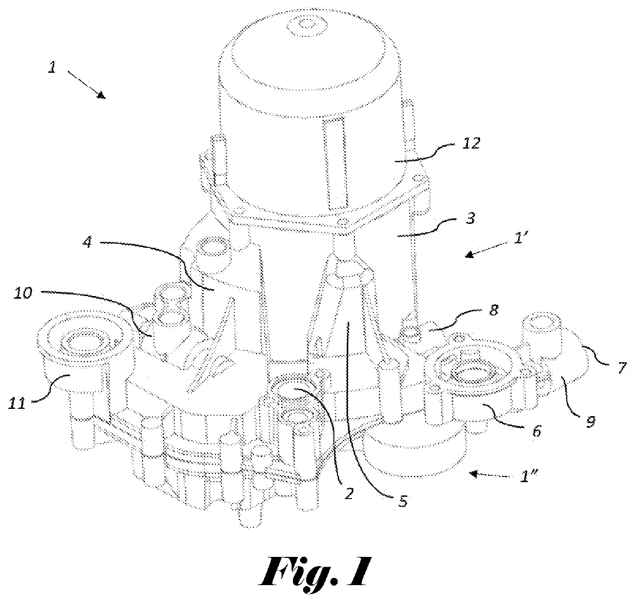
[0089]The housing 1 in FIG. 1 is provided with an inlet 2 for the gas-liquid mixture.

[0090]A liquid separation vessel 3 is integrated as a component of the housing 1, which liquid separator vessel is configured to separate liquid from the gas-liquid mixture.

[0091]In this case, the housing 1 also comprises additional integrated components, such as[0092]a liquid storage reservoir 4, which is configured such that it is able to store liquid from the liquid separator vessel 3;[0093]a liquid buffer tank 5, which is partly separated from the liquid separator vessel 3 by means of a wall of the liquid separator vessel 3, and which is configured such that liquid in the liquid separator vessel 3 may flow into the liquid buffer tank 5 and vice versa through an opening in said wall of the liquid separator vessel 3;[0094]a supporting seat 6, which is configured to accommodate an external liquid separation filter configured to further separate liquid from purified gas coming from the liquid separa...


PUM

PropertyMeasurementUnit
pressureaaaaaaaaaa
lengthaaaaaaaaaa
diameteraaaaaaaaaa

Abstract

A housing of a liquid separation device that includes an inlet for the gas-liquid mixture and a set of integrated components, the set of integrated components includes a liquid separator vessel to separate liquid from the gas-liquid mixture, and the liquid separator vessel includes an entry port for the gas-liquid mixture, a liquid outlet port, and a gas outlet port. The set of integrated components includes a set of channels, where a wall of each channel is part of the housing, where the set of channels includes an inlet channel to guide the gas-liquid mixture from the inlet to the entry port and an outlet channel to guide gas from the gas outlet port away from the liquid separator vessel. The housing includes at least two opposite housing pieces which can be hermetically sealed together along a sealing line which is situated in a sealing face.

Description

CROSS REFERENCE TO RELATED APPLICATIONS[0001]This application claims the benefit of provisional application 62 / 731,178, filed Sep. 14, 2018, and Belgium application BE 2019 / 5012, filed Jan. 10, 2019, which are incorporated herein by reference.[0002]The present invention concerns a housing of a liquid separation device for separation of a liquid from a gas-liquid mixture.[0003]In particular, the invention concerns a housing of a liquid separation device comprising an integrated liquid separation vessel as part of the housing for separating liquid from a gas compressed by means of a liquid-injected compressor or vacuum pump element.BACKGROUND[0004]It is known that, for such a compressor or vacuum pump element, liquid is injected into a compression chamber of the compressor or vacuum pump element to lubricate, cool and / or seal one or more rotors contained in this compression chamber.[0005]This liquid is mixed with the gas drawn into the compression chamber, and is discharged together w...

Claims


Application Information

Patent Timeline
Patent Type & Authority Applications(United States)
IPC IPC(8): B01D35/26B01D29/00B01D35/30B01D29/56
CPCB01D35/26B01D19/0031B01D29/56B01D29/009B01D35/30F04B39/02F04B39/062F04B39/16B01D46/0039B01D46/0002B01D46/0031B01D17/0211B01D46/0027F04D31/00B01D29/88
Inventor DOM, JOHANMOENS, BENJAMINBELLES, PIETER-JANTRUYEN, DIEGO
Owner ATLAS COPCO AIRPOWER NV
Why Eureka
Try Eureka