Supercharge Your Innovation With Domain-Expert AI Agents!

Method and apparatus for physical layer security communication in wireless communication system

Active Publication Date: 2020-03-19
ELECTRONICS & TELECOMM RES INST
View PDF6 Cites 6 Cited by
  • Summary
  • Abstract
  • Description
  • Claims
  • Application Information

AI Technical Summary

Benefits of technology

The present patent provides an apparatus and method for secure communication in a wireless communication system without additional channel information or a shared key. The method involves transmitting a preamble sequence to a base station and identifying a first frequency region and a second frequency region in which signals with a certain amplitude and phase are received. The base station then transmits a UL control signal with the identified frequency regions to the terminal. The terminal transmits a UL transmission signal with the data signal and jamming signal through the UL channel. The method ensures that the data signal is transmitted through the first frequency region and the jamming signal is transmitted through the second frequency region. The identification information can be transmitted through a physical uplink shared channel or a signal field in the preamble of a frame. The technical effect of the invention is to enhance security in wireless communication without compromising data transmission efficiency.

Problems solved by technology

However, the security scheme utilizing the security key has a problem in that security cannot be maintained when the security key shared by the transmitted and the receiver is leaked.
In addition, a physical layer security scheme has a disadvantage in that it is possible to optimally design the transmitter by knowing channel information between the transmitter and an eavesdropper.
However, in the physical layer security scheme, there is a problem in that the transmitter should use a plurality of antennas to maintain security when the transmitter does not know the channel between the transmitter and the eavesdropper.
In addition, the physical layer security scheme has a problem in that security cannot be maintained also when the number of antennas of the eavesdropper exceeds the number of antennas of the transmitter.
Accordingly, the physical layer security scheme has a problem in that the maintenance of security is limited in a bi-directional communication environment depending on the number of antennas of the transmitter.

Method used


Image

  • Method and apparatus for physical layer security communication in wireless communication system
  • Method and apparatus for physical layer security communication in wireless communication system
  • Method and apparatus for physical layer security communication in wireless communication system

Examples


first embodiment

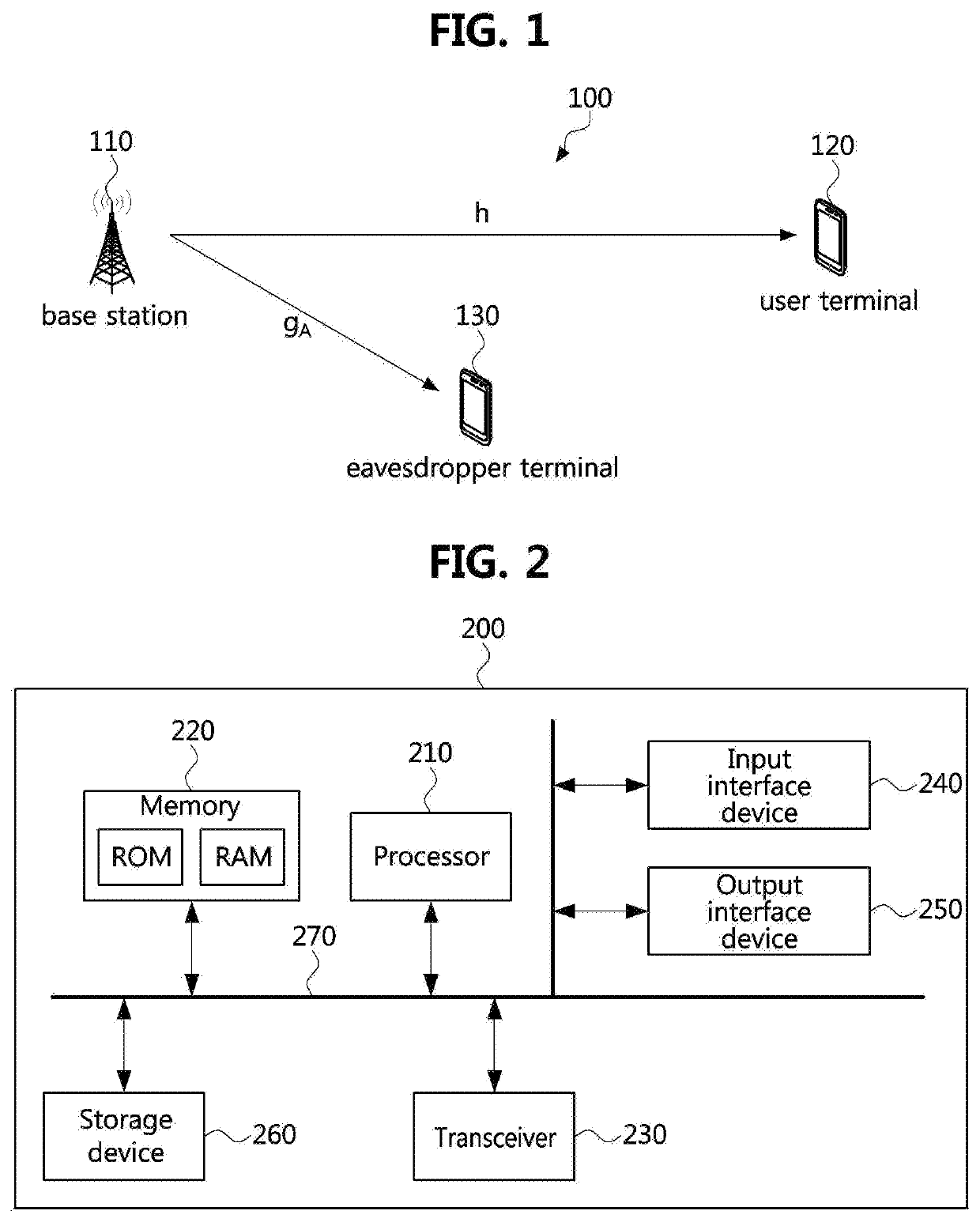
[0042]The present disclosure relates to a data transmission and reception method using a physical layer security (PHYSEC) scheme, in which a transmitter and a receiver can perform secure communications using a radio channel characteristic of a physical layer without sharing a secret key. In the physical layer security scheme, a radio channel itself between the transmitter and the receiver may operate as a security key. Accordingly, since there is no security key in the physical layer security scheme, there is no fear that the security key will be leaked. First, a wireless communication system according to the present disclosure will be described with reference to FIG. 1.

[0043]FIG. 1 is a conceptual diagram illustrating a wireless communication system according to a first embodiment of the present disclosure.

[0044]Referring to FIG. 1, a wireless communication system 100 may comprise a base station 110, a user terminal 120, and an eavesdropper terminal 130.

[0045]Each of the base stati...

second embodiment

[0114]A wireless communication system according to the present disclosure may operate in an in-band full-duplex (IFD) scheme. The IFD scheme will be described with reference to FIG. 6 below.

[0115]FIG. 6 is a conceptual diagram illustrating an environment where a physical layer security communication is performed in a wireless communication system according to a second embodiment of the present disclosure.

[0116]Referring to FIG. 6, a wireless communication system 600 may include a base station 610, a user terminal 620, and an eavesdropper terminal 630. Here, a structure of each of the base station 610, the user terminal 620, and the eavesdropper terminal 630 may be the same as or similar to the structure of the communication node 200 of FIG. 2.

[0117]The wireless communication system 600 may operate in the IFD scheme. For example, the base station 610 and the user terminal 620 may transmit and receive data in a channel h simultaneously. Here, the channel h may mean a channel between t...

third embodiment

[0145]FIG. 8 is a conceptual diagram illustrating an environment where a physical layer security communication is performed in a wireless communication system according to the present disclosure.

[0146]Referring to FIG. 8, a wireless communication system 600 may include a base station 810, a first user terminal 820, a second user terminal 830, and an eavesdropper terminal 840. Here, a structure of each of the base station 810, the first user terminal 820, the second user terminal 830, and the eavesdropper terminal 840 may be the same as or similar to the structure of the communication node 200 of FIG. 2.

[0147]The wireless communication system 800 may operate in the IFD scheme. For example, base station 810 may transmit a DL signal to the first user terminal 820 through a downlink channel hD. At the same time, the base station 810 may receive a UL signal from the second user terminal 830 through an uplink channel hU. Here, the first user terminal 820 may be referred to as a DL termina...


PUM


Abstract

An operation method of a terminal in a wireless communication system includes receiving a preamble sequence from a base station; estimating a UL channel between the terminal and the base station based on the preamble sequence; determining a first frequency region for transmitting a data signal and a second frequency region for transmitting a jamming signal in an entire frequency region of the UL channel based on a result of estimating the UL channel; and transmitting to the base station a UL control signal including identification information for identifying the first frequency region and the second frequency region.

Description

CROSS-REFERENCE TO RELATED APPLICATION[0001]This application claims priority to Korean Patent Application No. 10-2018-0112109, filed on Sep. 19, 2018 in the Korean Intellectual Property Office (KIPO), the entire content of which is hereby incorporated by reference.BACKGROUND1. Technical Field[0002]The present disclosure relates to a wireless communication system, and more particularly, to an apparatus and a method for physical layer security communication.2. Description of Related Art[0003]Generally, in a wireless communication system, a security scheme utilizing a security key shared by a transmitter and a receiver may be utilized to prevent eavesdropping and radio monitoring. However, the security scheme utilizing the security key has a problem in that security cannot be maintained when the security key shared by the transmitted and the receiver is leaked.[0004]In addition, a physical layer security scheme has a disadvantage in that it is possible to optimally design the transmitt...

Claims


Application Information

Patent Timeline
IPC IPC(8): H04K3/00H04L25/02H04L5/00
CPCH04L25/0228H04K2203/32H04K3/40H04L5/0007H04L5/0053H04K2203/36H04L25/022H04L27/2602H04L27/2646H04L63/1475H04L5/0048H04L5/0094H04W12/122
Inventor JU, HYUNG SIK
Owner ELECTRONICS & TELECOMM RES INST
Features
  • R&D
  • Intellectual Property
  • Life Sciences
  • Materials
  • Tech Scout
  • Unparalleled Data Quality
  • Higher Quality Content
  • 60% Fewer Hallucinations
Learn More