Al technical title is built by PatSnap Al team. It summarizes the technical point description of the patent document.
a technology of rotary wipers and wipers, which is applied in the direction of vehicle cleaning, instruments, and reradiation, etc., can solve the problems of affecting the function of sensor components, and affecting the cleaning effect of the vehicl
Active Publication Date: 2020-03-26
WAYMO LLC
View PDF0 Cites 12 Cited by
Summary
Abstract
Description
Claims
Application Information
AI Technical Summary
This helps you quickly interpret patents by identifying the three key elements:
Problems solved by technology
Method used
Benefits of technology
[0004]Aspects of the disclosure provide a system comprising a plurality of windows spaced around a sensor housing; a plurality of wipers positioned around the sensor housing, each of the wipers includes a wiper blade configured to clean a corresponding window of the plurality of windows; a drive system including a movable part coupled to a motor; and the motor configured to drive the drive system to simultaneously rotate the plurality of wipers around the sensor housing such that the plurality of wipers remove debris from the plurality of windows.
Problems solved by technology
However, these vehicles are often subjected to environmental elements such as rain, snow, dirt, etc., which can cause a buildup of debris and contaminants on these sensors.
Typically, the sensors include a cover or an aperture to protect the internal sensor components of the sensors from the debris and contaminants, but over time, the cover itself may become dirty.
As such, the functions of the sensor components may be impeded as signals transmitted and received by the internal sensor components are blocked by the debris and contaminants.
Method used
Image
Click on the blue label to locate the original text in one second.
Reading with bidirectional positioning of images and text.
Examples
Embodiment Construction
Overview
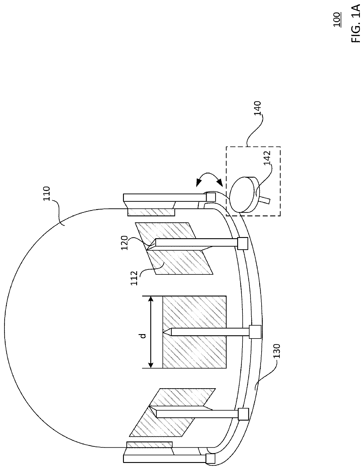
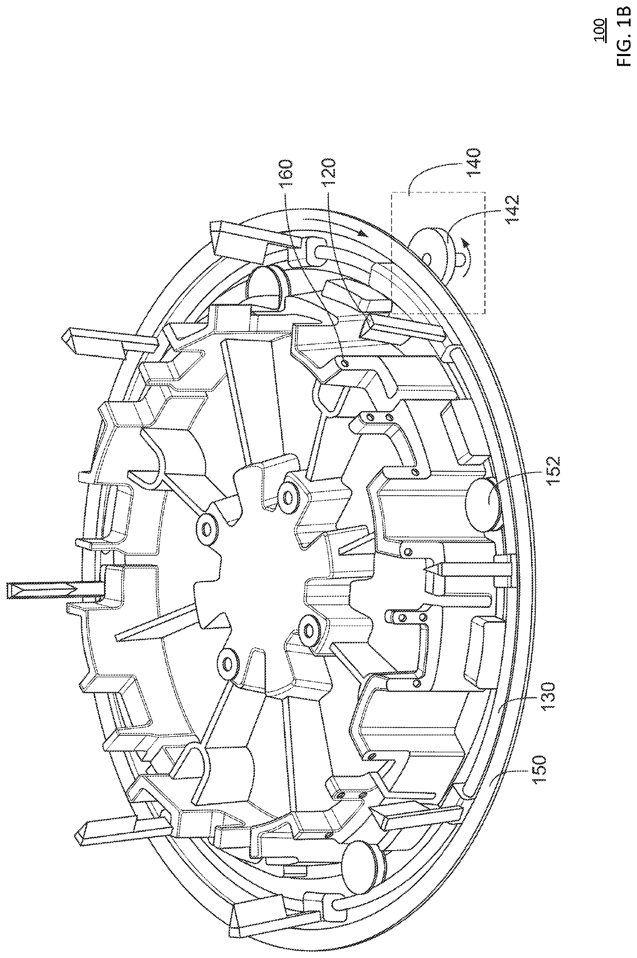
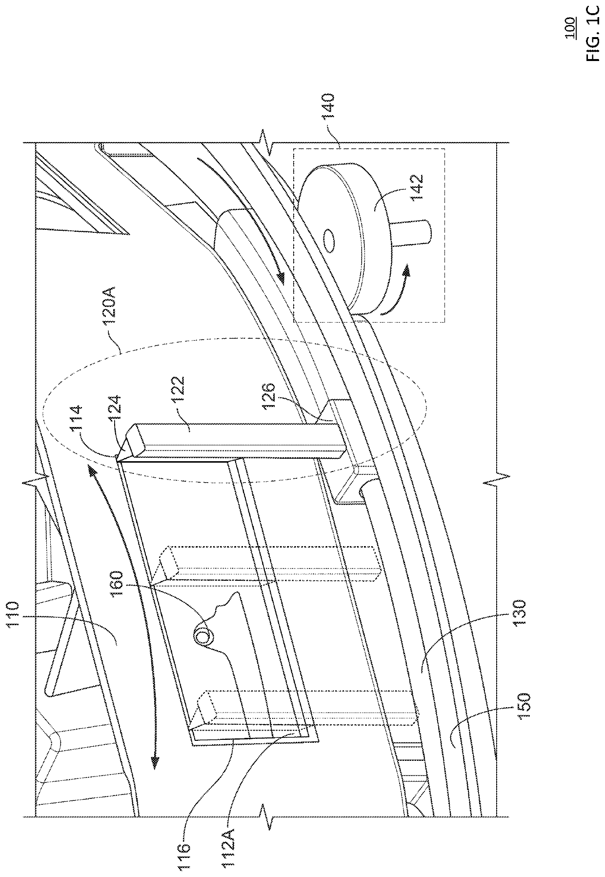
[0024]The technology generally relates to a wiper system for cleaning a surface of a sensor housing, such as a sensor housing positioned on top of a vehicle. For example, the sensor housing may be a dome, a cylinder, polygonal, or some other shape. Various camera / sensor equipment may transmit and receive signals through windows on the sensor housing. The functions of the camera / sensor equipment may be impacted as debris and contaminants accumulate on these windows. To address this, a wiper system is provided to wipe the debris and contaminants off the windows of the sensor housing. The wiper system includes a plurality of wipers positioned around a circumference of a sensor housing, a motor, and a drive system configured to move the wipers between various positions around the circumference of the sensor housing.
[0025]The wiper system includes a wiper ring to support the plurality of wipers and to enable their movements around the circumference of the sensor housing. In this ...
PUM
Abstract
The disclosure provides for a wiper system for cleaning a surface of a sensor housing, such as a sensor housing positioned on top of a vehicle. The wiper system includes a plurality of windows spaced around a sensor housing, and a plurality of wipers positioned around the sensor housing, each of the wipers includes a wiper blade configured to clean a corresponding window of the plurality of windows. The wiper system further includes a drive system including a movable part coupled to a motor. The motor is configured to drive the drive system to simultaneously rotate the plurality of wipers around the sensor housing such that the plurality of wipers remove debris from the plurality of windows.
Description
CROSS-REFERENCE TO RELATED APPLICATIONS[0001]This application claims the benefit of the filing date of U.S. Provisional Patent Application No. 62 / 736,573 filed Sep. 26, 2018, the disclosure of which is hereby incorporated herein by reference.BACKGROUND[0002]Various types of vehicles, such as cars, trucks, motorcycles, busses, boats, airplanes, helicopters, lawn mowers, recreational vehicles, amusement park vehicles, farm equipment, construction equipment, trams, golf carts, trains, trolleys, etc., may be equipped with various types of sensors in order to detect objects in the vehicle's environment. For example, vehicles, such as autonomous vehicles, may include such LIDAR, radar, sonar, camera, or other such imaging sensors that scan and record data from the vehicle's environment. Sensor data from one or more of these sensors may be used to detect objects and their respective characteristics (position, shape, heading, speed, etc.).[0003]However, these vehicles are often subjected to...
Claims
Application Information
Patent Timeline
Application Date:The date an application was filed.
Publication Date:The date a patent or application was officially published.
First Publication Date:The earliest publication date of a patent with the same application number.
Issue Date:Publication date of the patent grant document.
PCT Entry Date:The Entry date of PCT National Phase.
Estimated Expiry Date:The statutory expiry date of a patent right according to the Patent Law, and it is the longest term of protection that the patent right can achieve without the termination of the patent right due to other reasons(Term extension factor has been taken into account ).
Invalid Date:Actual expiry date is based on effective date or publication date of legal transaction data of invalid patent.
Patent Type & Authority Applications(United States)