Eureka AIR delivers breakthrough ideas for toughest innovation challenges, trusted by R&D personnel around the world.

Backlight module and display module

Active Publication Date: 2020-03-26
XIAMEN TIANMA MICRO ELECTRONICS
View PDF9 Cites 0 Cited by
  • Summary
  • Abstract
  • Description
  • Claims
  • Application Information

AI Technical Summary

Benefits of technology

The patent text describes a new type of backlight module used in electronic devices. The backlight module has multiple light-emitting units arranged in a row. Each unit has three separate structures that emit light in different directions. These structures are on two separate substrates that are placed opposite each other. The three structures produce light that doesn't overlap with each other, resulting in a more uniform backlight. This design allows for better control over the brightness and direction of the light emitted from the backlight. This technology is useful for improving the quality of electronic devices such as displays.

Problems solved by technology

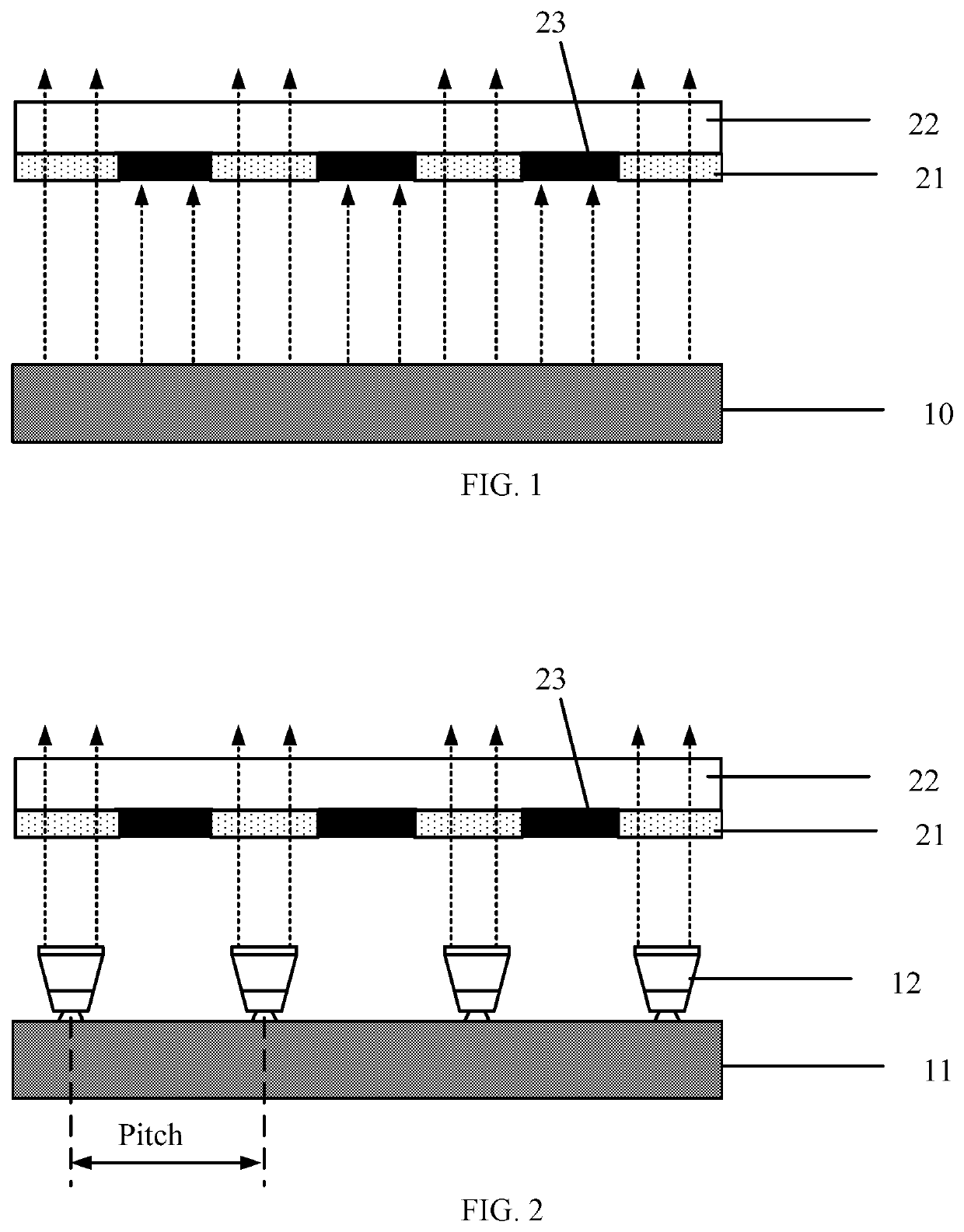
However, the thickness of the color resist is limited to 2.5 mm or less under the current level of the manufacturing process, which results in poor color gamut and chromaticity parameters of the display module.
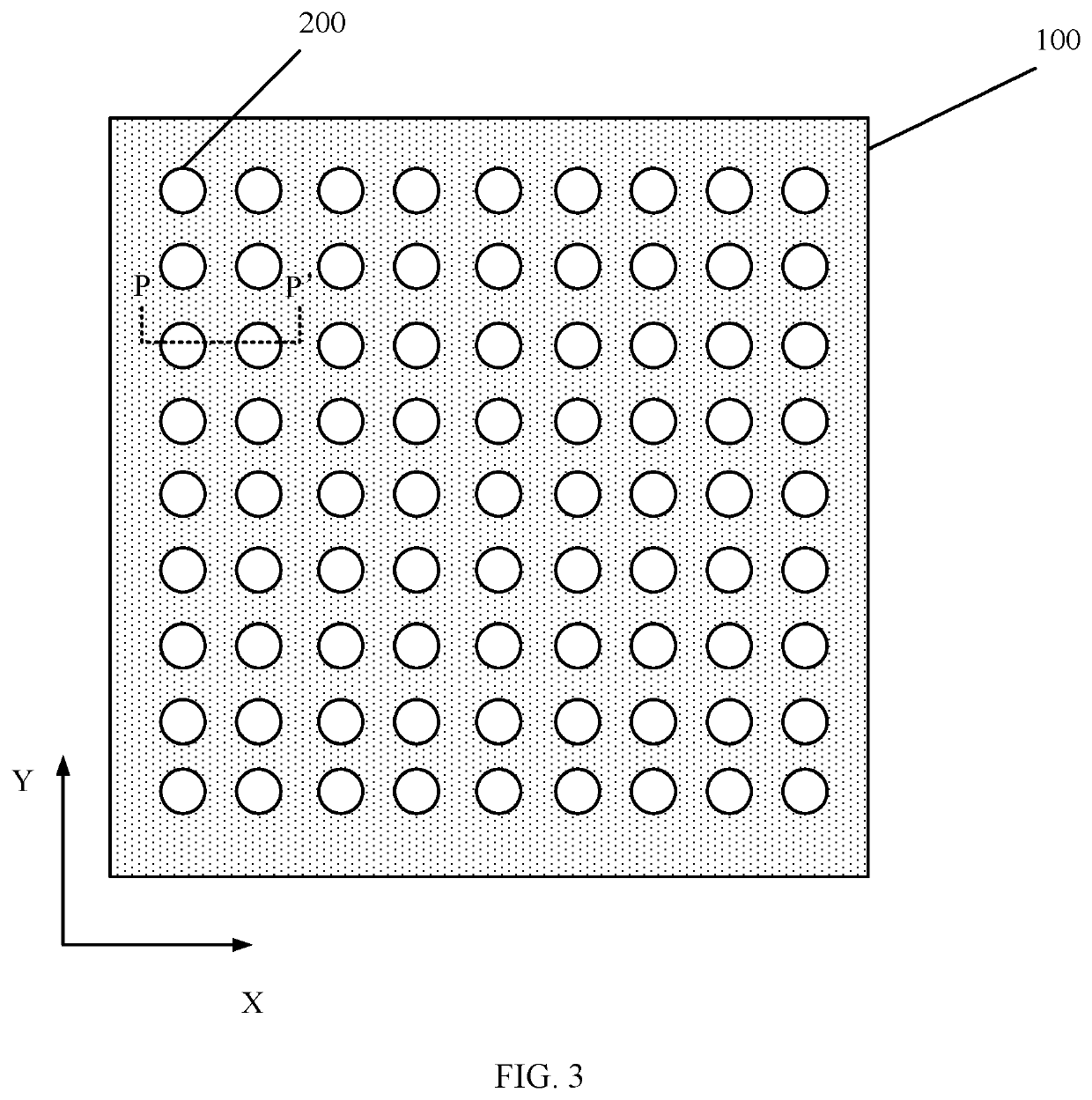
However, because the pitch between light-emitting structures that are arranged in an array needs to be set small, and the arrangement of the plurality of small-pitch light-emitting structures is difficult, the manufacturing yield of the backlight module is undesired.

Method used


Image

  • Backlight module and display module
  • Backlight module and display module
  • Backlight module and display module

Examples


Embodiment Construction

[0017]Various exemplary embodiments of the present disclosure will now be described in detail with reference to the accompanying drawings. It should be noted that the relative arrangement of the components and steps, numerical expressions and numerical values set forth in the embodiments are not intended to limit the scope of the present disclosure. The following description of the at least one exemplary embodiment is merely illustrative, and by no means can be considered as limitations for the application or use of the present disclosure.

[0018]It should be noted that techniques, methods, and apparatuses known to those of ordinary skill in the relevant art may not be discussed in detail, but where appropriate, the techniques, methods, and apparatuses should be considered as part of the specification.

[0019]In all of the examples shown and discussed herein, any specific values should be considered as illustrative only and not as a limitation. Therefore, other examples of exemplary emb...


PUM


Abstract

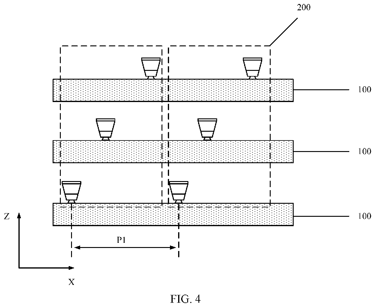
The present disclosure provides a backlight module and a display module. The backlight module includes a plurality of light-emitting units arranged in an array. Each light-emitting unit includes a first light-emitting structure, a second light-emitting structure, and a third light-emitting structure. The first light-emitting structure, the second light-emitting structure, and the third light-emitting structure are respectively disposed on at least two substrates that are arranged opposite to each other. Light emitted by the first light-emitting structure, light emitted by the second light-emitting structure, and light emitted by the third light-emitting structure are unoverlapped with each other.

Description

CROSS-REFERENCES TO RELATED APPLICATIONS[0001]This application claims the priority of Chinese patent application No. 201811099326.9, filed on Sep. 20, 2018, the entirety of which is incorporated herein by reference.FIELD OF THE DISCLOSURE[0002]The present disclosure generally relates to the field of display technology and, more particularly, relates to a backlight module and a display module.BACKGROUND[0003]A backlight is an important component of a passive light-emitting display module (such as a liquid crystal display module), and is used to provide a light source to assist a passive light-emitting element to implement the display function.[0004]A conventional backlight module is used to emit white light. In order to display a specific color, the white light emitted by the backlight module passes through a color resist disposed on an opposite substrate, such that a color light can be formed and transmitted out. Therefore, such a backlight module needs to be used with a color resis...

Claims


Application Information

Patent Timeline
IPC IPC(8): G02F1/1335
CPCG02F1/133606G02F1/136286G02F1/1368G02F2001/133614G02F1/133512G02F2001/133613G02F1/133514G02F1/133602G02F1/133607G02F1/133614G02F1/133608G02F1/133621G02F1/133613
Inventor LIU, BINGPING
Owner XIAMEN TIANMA MICRO ELECTRONICS
Why Eureka
Eureka Blog
Learn More