
Travel control apparatus for four-wheel drive vehicle

Active Publication Date: 2020-04-09
TOYOTA JIDOSHA KK
View PDF0 Cites 2 Cited by
  • Summary
  • Abstract
  • Description
  • Claims
  • Application Information

AI Technical Summary

Benefits of technology

The patent aims to improve the control of a vehicle when it is turning. The new system uses a specific ratio to increase the speed of the vehicle, which prevents the wheels from losing traction when the driver is not using the car's accelerator. This results in better handling and reduced chances of the vehicle getting into a dangerous situation.

Problems solved by technology

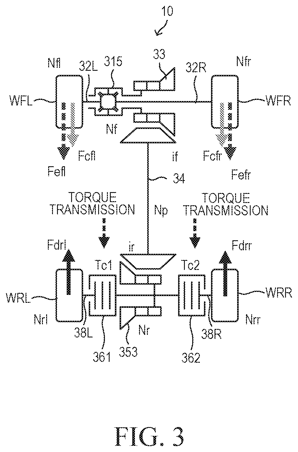
However, when the accelerator pedal is not operated (when accelerator opening is zero), the driving forces of the front wheels disappear, and instead, braking force attributable to engine braking is generated.
As a result, the maximum lateral force that each front wheel can generate (hereinafter also referred to as “lateral force margin”) decreases, which may create conditions under which the vehicle easily causes understeer behavior.
The greater the magnitude of deceleration of the four-wheel drive vehicle, the greater the possibility of occurrence of spontaneous inward turning.
If the yaw moment control by driving force is performed in a state in which the spontaneous inward turning easily occurs, the behavior of the four-wheel drive vehicle may become unstable.
Further, when a large deceleration is generated as a result of the brake pedal being operated, understeer behavior may occur because of decrease of the lateral force margins of the primary drive wheels.

Method used


Image

  • Travel control apparatus for four-wheel drive vehicle
  • Travel control apparatus for four-wheel drive vehicle
  • Travel control apparatus for four-wheel drive vehicle

Examples


first embodiment

(Configuration)

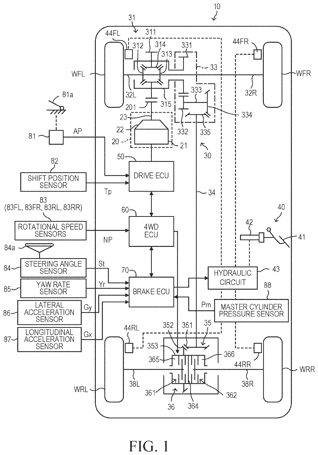
[0040]A travel control apparatus for a four-wheel drive vehicle according to a first embodiment of the present disclosure (hereinafter also referred to as the “first apparatus”) is applied to a four-wheel drive vehicle (vehicle) 10 as shown in FIG. 1.

[0041]The vehicle 10 includes a drive apparatus 20, a power transmission apparatus 30, a brake apparatus 40, a drive ECU 50, a 4WD ECU 60, a brake ECU 70.

[0042]The drive apparatus 20 includes an engine main body 21, a primary transmission 22, and an output shaft 23. The engine main body 21 is a spark-ignition-type multi-cylinder internal combustion engine. The drive apparatus 20 generates driving force for driving wheels (a front left wheel WFL, a front right wheel WFR, a rear left wheel WRL, and a rear right wheel WRR) of the vehicle 10. The primary transmission 22 is an automatic transmission which changes the gear (gear ratio) in accordance with the travel state of the vehicle 10. The driving force generated by the eng...

second embodiment

[0124]Next, a travel control apparatus for a four-wheel drive vehicle according to a second embodiment of the present disclosure (hereinafter referred to as the “second apparatus”) will be described. The second apparatus differs from the first apparatus only in the point that, even in the case where the vehicle is turning and the magnitude |Gy| of the lateral acceleration is less than the predetermined lateral acceleration threshold Gyth, the second apparatus immediately stops the yaw moment control by driving force (performs the torque transmission interruption control) when the actual yaw rate of the vehicle 10 has deviated from a normative yaw rate. Accordingly, this difference will be mainly described below.

[0125]A normative yaw rate Ym is calculated in accordance with the following Expression (5). In Expression (5), N is the steering gear ratio of the steering wheel 84a, L is the wheelbase of the vehicle 10, and Kh is the stability factor of the vehicle 10. Namely, the normativ...

third embodiment

[0139]Next, a travel control apparatus for a four-wheel drive vehicle according to a third embodiment of the present disclosure (hereinafter referred to as the “third apparatus”) will be described. The third apparatus differs from the first apparatus only in the point that, even in the case where none of the accelerator pedal 81a and the brake pedal 41 is operated, the vehicle 10 is turning, and the magnitude |Gy| of the lateral acceleration of the vehicle 10 is less than the predetermined lateral acceleration threshold Gyth in such a state, the third apparatus performs the torque transmission interruption control when the magnitude |Gx| of the longitudinal acceleration of the vehicle 10 is equal to or greater than a predetermined longitudinal acceleration threshold Gxth. Accordingly, this difference will be mainly described below.

[0140]As described above, when the driver suddenly releases the accelerator pedal while the vehicle 10 is turning, spontaneous inward turning may occur. A...


PUM


Abstract

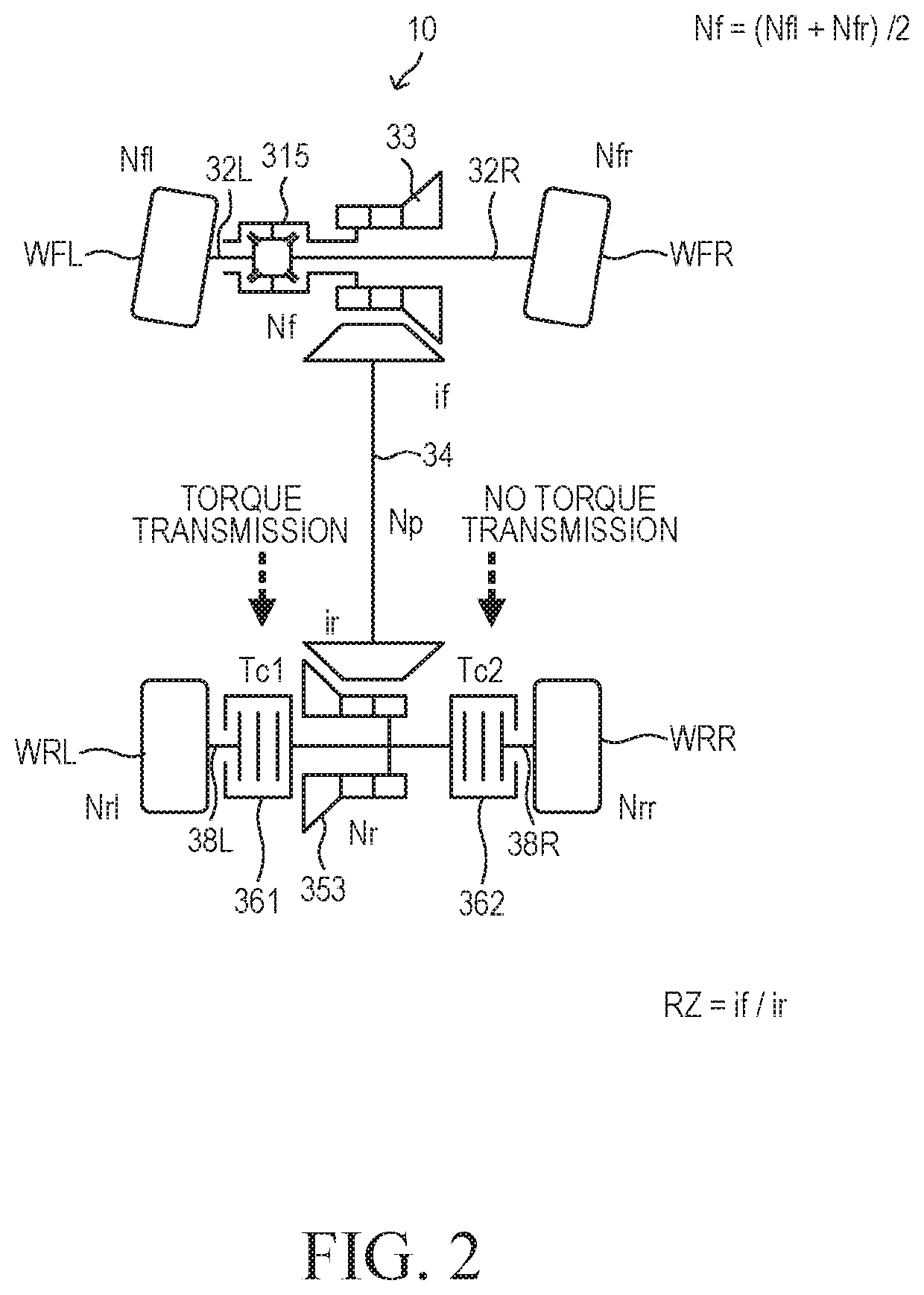
Disclosed is a travel control apparatus for a four-wheel drive vehicle in which the states of engagements between a drive output part for secondary drive wheels and left and right secondary drive wheel axles are each changed to a torque transmission state or a torque transmission interruption state. The ratio of rotational speed of the drive output part to the average of rotational speeds of primary drive wheels is greater than 1. When the engagement states corresponding to the secondary drive wheels on the outer and inner sides of a turning locus have been set to the torque transmission state and the torque transmission interruption state, respectively, the engagement state having been set to the torque transmission state is changed to the torque transmission interruption state upon determination that an accelerator pedal is not operated and the magnitude of lateral acceleration is equal to or greater than a predetermined threshold.

Description

CROSS-REFERENCE TO RELATED APPLICATION[0001]This application claims priority to Japanese Application No. 2018-190632 filed on Oct. 9, 2018, the entire contents of which are incorporated by reference.BACKGROUND1. Technical Field[0002]The present disclosure relates to a travel control apparatus applied to a four-wheel drive vehicle which includes a differential apparatus for transmitting driving force generated by a drive apparatus to left and right primary drive wheels, and a final gear apparatus for secondary drive wheels for transmitting the driving force to left and right secondary drive wheels.2. Description of the Related Art[0003]In a conventionally known four-wheel drive vehicle, a first coupling apparatus is disposed between a left secondary drive wheel axle and a drive output part of a final gear apparatus for secondary drive wheels, and a second coupling apparatus is disposed between a right secondary drive wheel axle and the drive output part. The secondary drive wheels ar...

Claims


Application Information

Patent Timeline
IPC IPC(8): B60K23/08F16H48/05B60K17/346
CPCB60K17/346B60K2023/0825B60K23/0808B60K2023/043F16H48/05F16H48/19B60K17/35B60K23/08B60K2023/0833B60K23/04B60K2023/0858B60Y2400/424B60W2520/125
Inventor IWAZAKI, NORITSUGUSUETAKE, YUSUKE
Owner TOYOTA JIDOSHA KK
Learn More