
Popcorn pot designed to gravitate oil and kernels to the center of heat source

a technology of kernels and heat sources, applied in the field of kernel pots, can solve the problems of unconcentrated heat distribution, kernels that burn or not pop, and current systems that do not work well

Active Publication Date: 2020-04-16
GAJEWSKI JENNIFER LYNN
View PDF0 Cites 0 Cited by
  • Summary
  • Abstract
  • Description
  • Claims
  • Application Information

AI Technical Summary

Benefits of technology

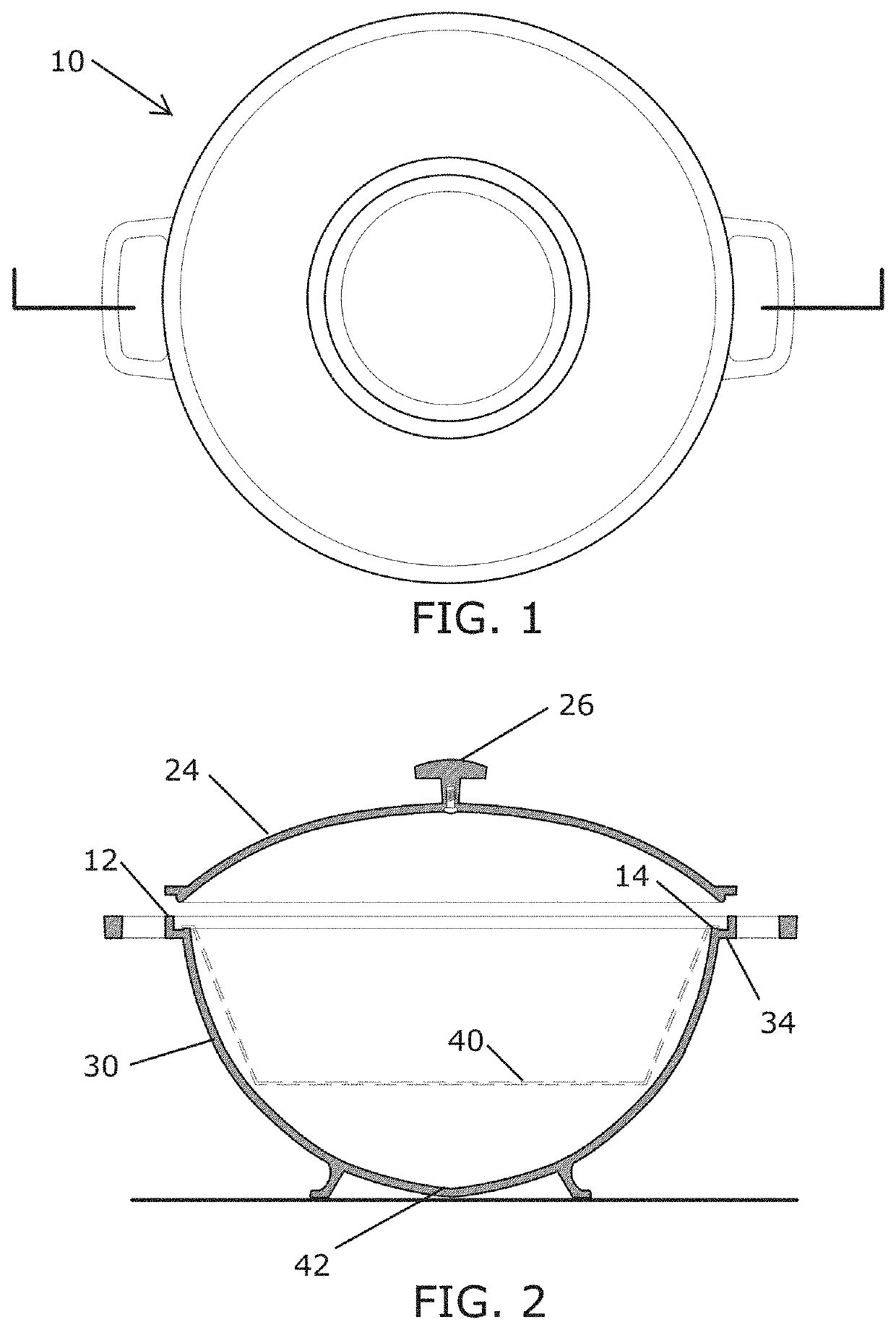
The present invention is a popcorn pot with a curved body and a domed lid that can be closed over the cavity opening. The pot has a stabilizing footing that can be placed on a heating element and an integral footing that provides a flat surface for engaging level surfaces. The pot has a paraboloid-shaped cavity that is thermally defined at the bottom and the contents of the cavity expand as they cook. The pot is designed to maximize the surface area of the cavity and prevent the contents from burning. The invention also includes a method for popping popcorn in the pot. The technical effects of the invention include improved cooking efficiency, reduced risk of burning, and a more consistent texture of the popcorn.

Problems solved by technology

When popping popcorn in a flat-bottom pot such as a sauté pan or sauce pot, problematically, kernels can scatter across the flat-bottom, resulting in kernels that burn or do not pop due to two main factors: 1) unconcentrated heat distribution and 2) inadequate oil coverage.
In short, the current systems do not work well because the flat-bottom popcorn pot is labor intensive, noisy, inefficient, wasteful, and ultimately unpredictable because the quality of the popped popcorn depends not only on the experience level of the person making the popcorn but also on their physical capabilities, as the current solutions are limiting in the case of operability by the physically disabled.

Method used


Image

  • Popcorn pot designed to gravitate oil and kernels to the center of heat source
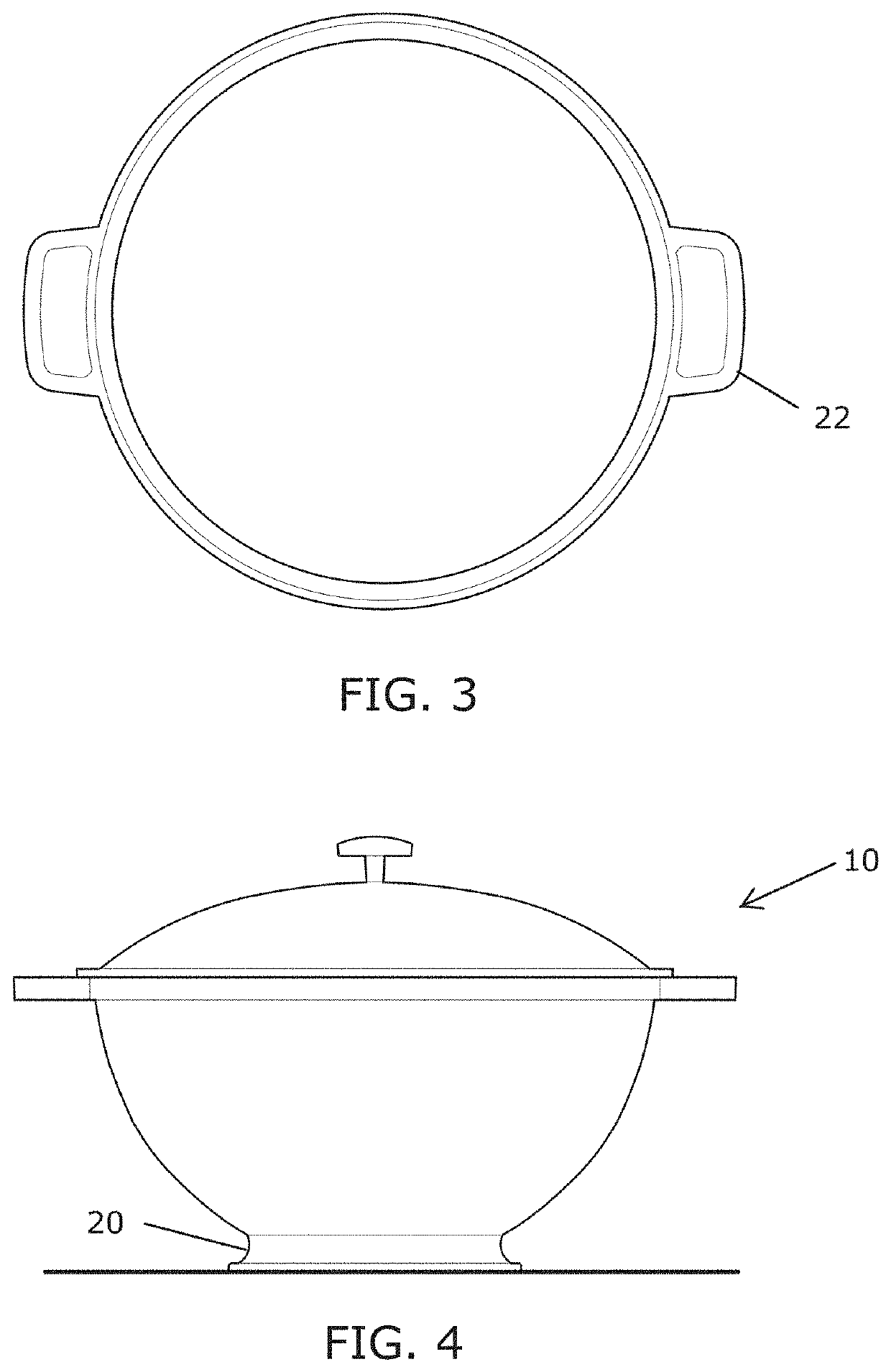
  • Popcorn pot designed to gravitate oil and kernels to the center of heat source
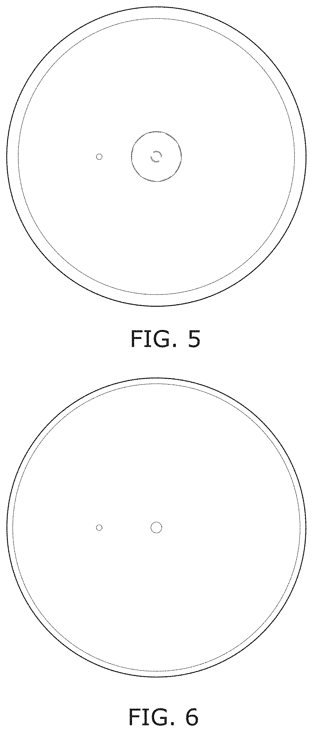
  • Popcorn pot designed to gravitate oil and kernels to the center of heat source

Examples


Embodiment Construction

[0023]The following detailed description identifies the best currently contemplated mode of carrying out exemplary embodiments of the invention. The description is not to be taken in a limiting sense, but is made merely for the purpose of illustrating the general principles of the invention, since the scope of the invention is best defined by the appended claims.

[0024]Broadly, an embodiment of the present invention provides a popcorn pot having a paraboloid-shaped cavity for gravitationally concentrating the un-popped kernels and depth of oil over the center of the heat source, thereby providing more predictable results with a method of greater efficiency than a flat-bottomed pot, while using less oil for healthier results. A footing is provided along a lower portion of the popcorn pot for stabilizing the curvilinear body on a flat-top heat source. A domed lid for covering the opening communicating to the paraboloid-shaped cavity is provided for effectuating convection heating withi...


PUM


Abstract

A popcorn pot having a curvilinear body providing a paraboloid-shaped cavity for gravitationally concentrating a quantity of un-popped kernels and a depth of oil over a bottom center of the popcorn pot. The curvilinear body provides volumetric containment inside the paraboloid cavity. Integral footing along a lower portion of the popcorn pot stabilizes the curvilinear body over a flat-top heat source so that the bottom center is disposed centrally thereover. The popcorn pot may include a domed lid for covering the opening communicating to the paraboloid-shaped cavity, wherein the lid is adapted to effectuate convection heating within the cavity, thereby providing natural efficiency and universal accessibility with more predictable results than a flat-bottomed pot, while using less oil for healthier results.

Description

CROSS-REFERENCE TO RELATED APPLICATION[0001]This application claims the benefit of priority of U.S. provisional application No. 62 / 645,441, filed 20 Mar. 2018, the contents of which are herein incorporated by reference.BACKGROUND OF THE INVENTION[0002]The present invention relates to popcorn pots and, more particularly, to a popcorn pot designed to gravitate oil and kernels to the center of a flat-top heat source.[0003]When popping popcorn in a flat-bottom pot such as a sauté pan or sauce pot, problematically, kernels can scatter across the flat-bottom, resulting in kernels that burn or do not pop due to two main factors: 1) unconcentrated heat distribution and 2) inadequate oil coverage.[0004]Current stovetop popcorn pots are designed with a flat bottom to conform to the flat top of the burner which, as stated above, causes kernels to scatter and burn if not constantly attended to. Current solutions to the problems associated with the flat-bottom pot involve adding extra parts to k...

Claims


Application Information

Patent Timeline
Patent Type & Authority Applications(United States)
IPC IPC(8): A47J27/00A23L7/183A47J36/08A47J36/02A23L5/10
CPCA47J36/08A23L5/12A23V2002/00A47J36/02A47J27/002A23L7/183A23L5/15A23L7/174
Inventor GAJEWSKI, JENNIFER LYNN
Owner GAJEWSKI JENNIFER LYNN
Learn More