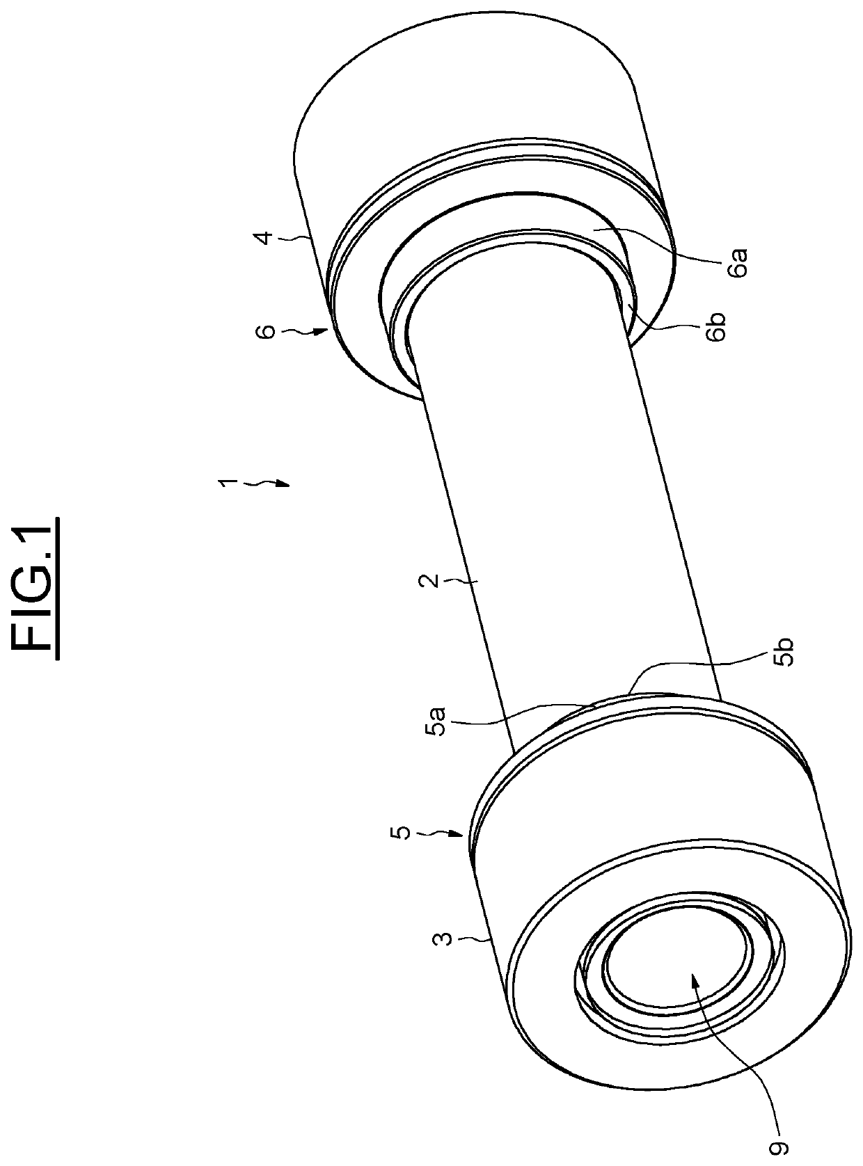
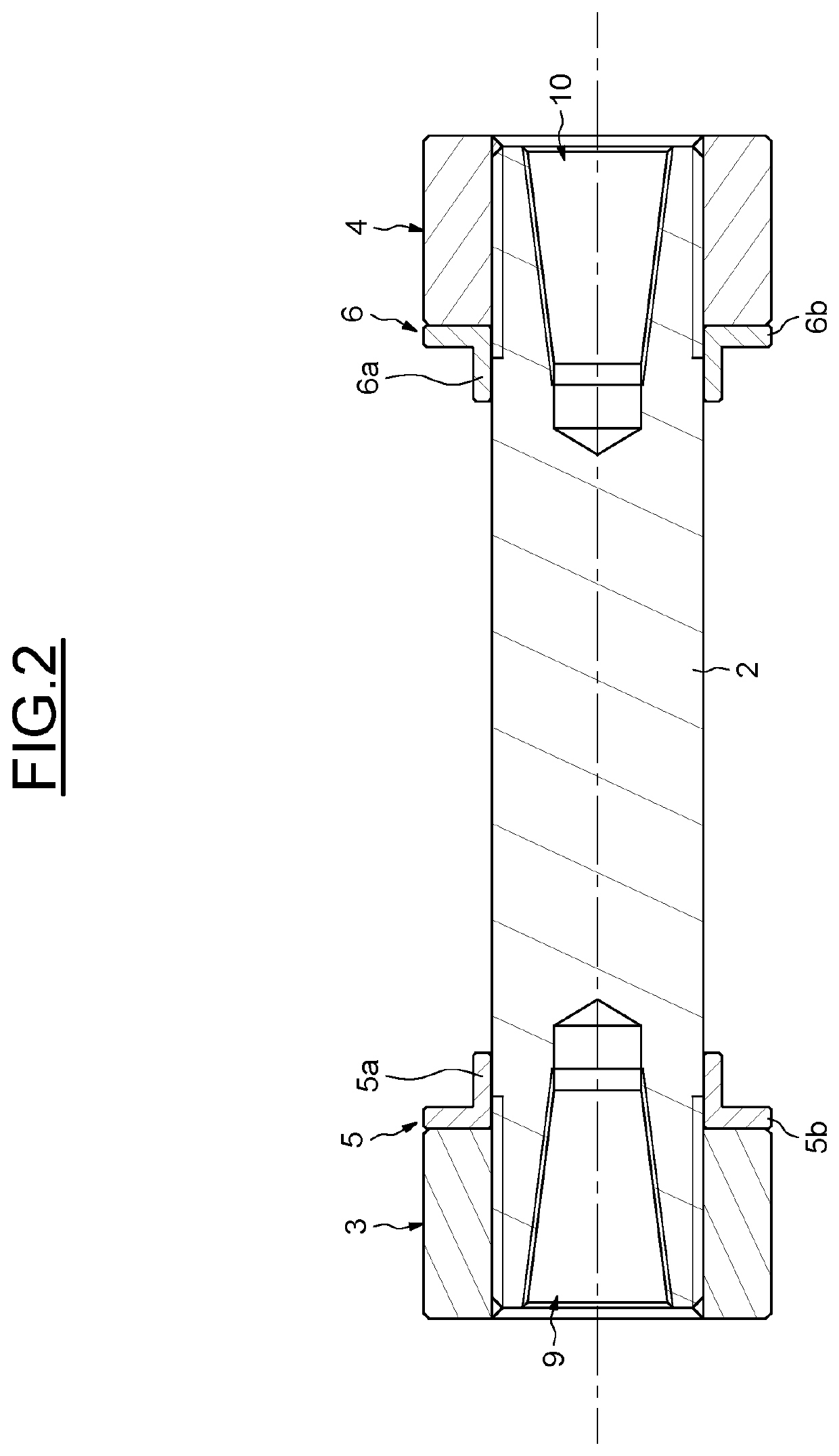
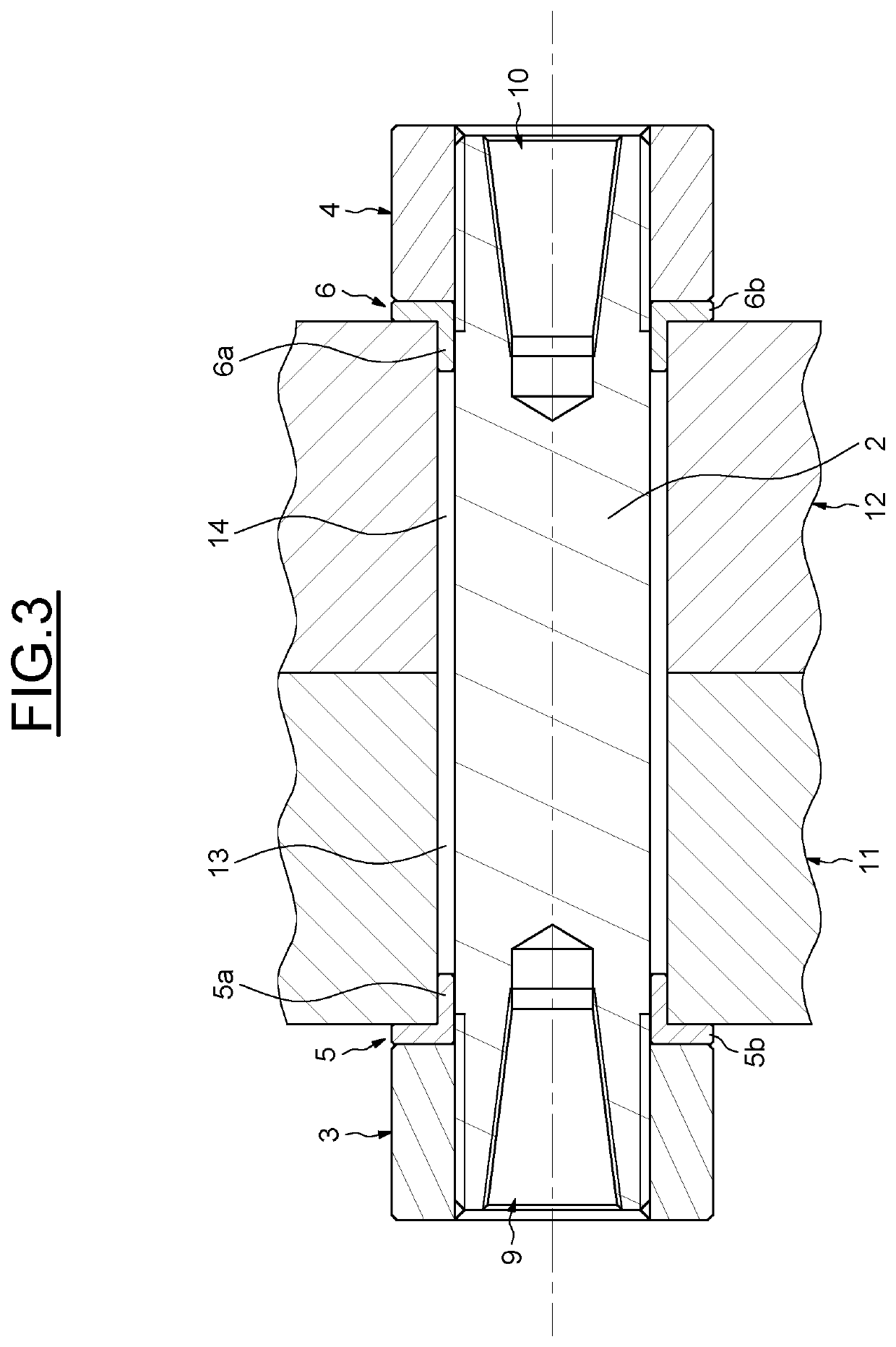
Clamp bolt and associated assembly

a technology of clamping bolts and bolts, which is applied in the direction of washers, rod connections, screws, etc., can solve the problems of high cost, inability to easily de-tension, and the inability to implement expansion bolts. to work, and the tolerances of coupling holes are very tight for the implementation of expansion bolts

Pending Publication Date: 2022-09-29
PILGRIM INT LTD
View PDF0 Cites 0 Cited by
  • Summary
  • Abstract
  • Description
  • Claims
  • Application Information

AI Technical Summary

Problems solved by technology

When a high torque is transmitted through the couplings, the couplings may slip so that clearance fit bolting becomes stuck and cannot be de-tensioned easily.
However, implementing expansion bolts requires very tight coupling hole tolerances to work and are expensive.

Method used


Image

  • Clamp bolt and associated assembly
  • Clamp bolt and associated assembly
  • Clamp bolt and associated assembly

Examples


Embodiment Construction

[0031]Those of ordinary skill in the art will appreciate from this disclosure that when a range is provided such as (for example) an angle / distance / number / weight / volume / spacing being between one (1 of the appropriate unit) and ten (10 of the appropriate units) that specific support is provided by the specification to identify any number within the range as being disclosed for use with a preferred embodiment. For example, the recitation of a percentage of copper between one percent (1%) and twenty percent (20%) provides specific support for a preferred embodiment having two point three percent (2.3%) copper even if not separately listed herein and thus provides support for claiming a preferred embodiment having two point three percent (2.3%) copper. By way of an additional example, a recitation in the claims and / or in portions of an element moving along an arcuate path by at least twenty) (20° degrees, provides specific literal support for any angle greater than twenty) (20° degrees,...


PUM


Abstract

A clamp bolt providing a bolt and two nut, each nut being screwed on an end of the bolt. The clamp bolt further including two washers, mounted around the bolt, and axially positioned between the two nuts.

Description

CROSS-REFERENCE TO RELATED APPLICATIONS[0001]This application claims priority to German Patent Application no. 102021202834.9, filed Mar. 23, 2021, the contents of which is fully incorporated herein by reference.TECHNICAL FIELD OF THE INVENTION[0002]The present invention relates to clamp bolts, and more particularly to clamp bolts for assembling at least two turbine parts.BACKGROUND OF THE INVENTION[0003]Generally, two turbine parts are coupled together with clearance fit bolting.[0004]When a high torque is transmitted through the couplings, the couplings may slip so that clearance fit bolting becomes stuck and cannot be de-tensioned easily.[0005]To avoid this, the torque capacities of clearance fit bolting couplings are small.[0006]One known solution to enhance torque capacity is to use expansion bolts to couple the two turbine parts.[0007]The expansion bolts expand inside and fill the coupling holes of the parts to prevent slipping.[0008]However, implementing expansion bolts requi...

Claims


Application Information

Patent Timeline
Patent Type & Authority Applications(United States)
IPC IPC(8): F16B19/02F16B4/00F16B5/02F16B7/02F16B7/14F16B23/00F16B35/00F16B35/04F16B37/04
CPCF16B19/02F16B4/004F16B5/0258F16B7/025F16B7/149F16B23/0061F16B35/005F16B35/041F16B37/042F16B37/046F16B35/00F16B35/04F16B37/00F16B5/0275F01D5/066F16B43/02F16B5/02F16B5/0642F01D25/246F05D2260/31
Inventor KITCHEN, JARED
Owner PILGRIM INT LTD
Why Eureka
Try Eureka