System and method for extending depth of field for 2d vision system cameras in the presence of moving objects

Pending Publication Date: 2022-01-13
COGNEX CORPORATION
View PDF0 Cites 0 Cited by
  • Summary
  • Abstract
  • Description
  • Claims
  • Application Information

AI Technical Summary

Benefits of technology

[0008]In an illustrative embodiment, a system and method for maximizing depth of field (DOF) with respect to an object imaged by a vision system camera, by projecting light from the object onto the image sensor along an optical path, and through a lens assembly of solid or glass lenses and a variable lens responsive to an image processor can be provided. In such a system and method, the optical path can be moved to a prevailing angle by a mechanical system that varies the optical path. The system and method can determine a distance between the object and an image plane of the vision system camera based upon constraints that can comprise (a) a speed of motion of the object, (b) a maximum size of the object, (c) and/or a minimum distance between the object and another adjacent object moving at the speed of motion. The prevailing angle of the optical path can be determined with respect to the image plane. The variable lens can be set to focus the projected light with respect to a plane of interest on the object. An image can then be acquired with the vision system camera. Illustratively, the mechanical system can vary an angle the optical path by tilting the lens assembly with respect to the housing, and/or the mechanical system can vary the angle of a steerable mi

Problems solved by technology

It can be challenging for the image sensor to focus in on the complete working range of the (typically moving) object in which an ID code may be located—p

Method used


Image

  • System and method for extending depth of field for 2d vision system cameras in the presence of moving objects
  • System and method for extending depth of field for 2d vision system cameras in the presence of moving objects
  • System and method for extending depth of field for 2d vision system cameras in the presence of moving objects

Examples


Embodiment Construction

I. System Overview

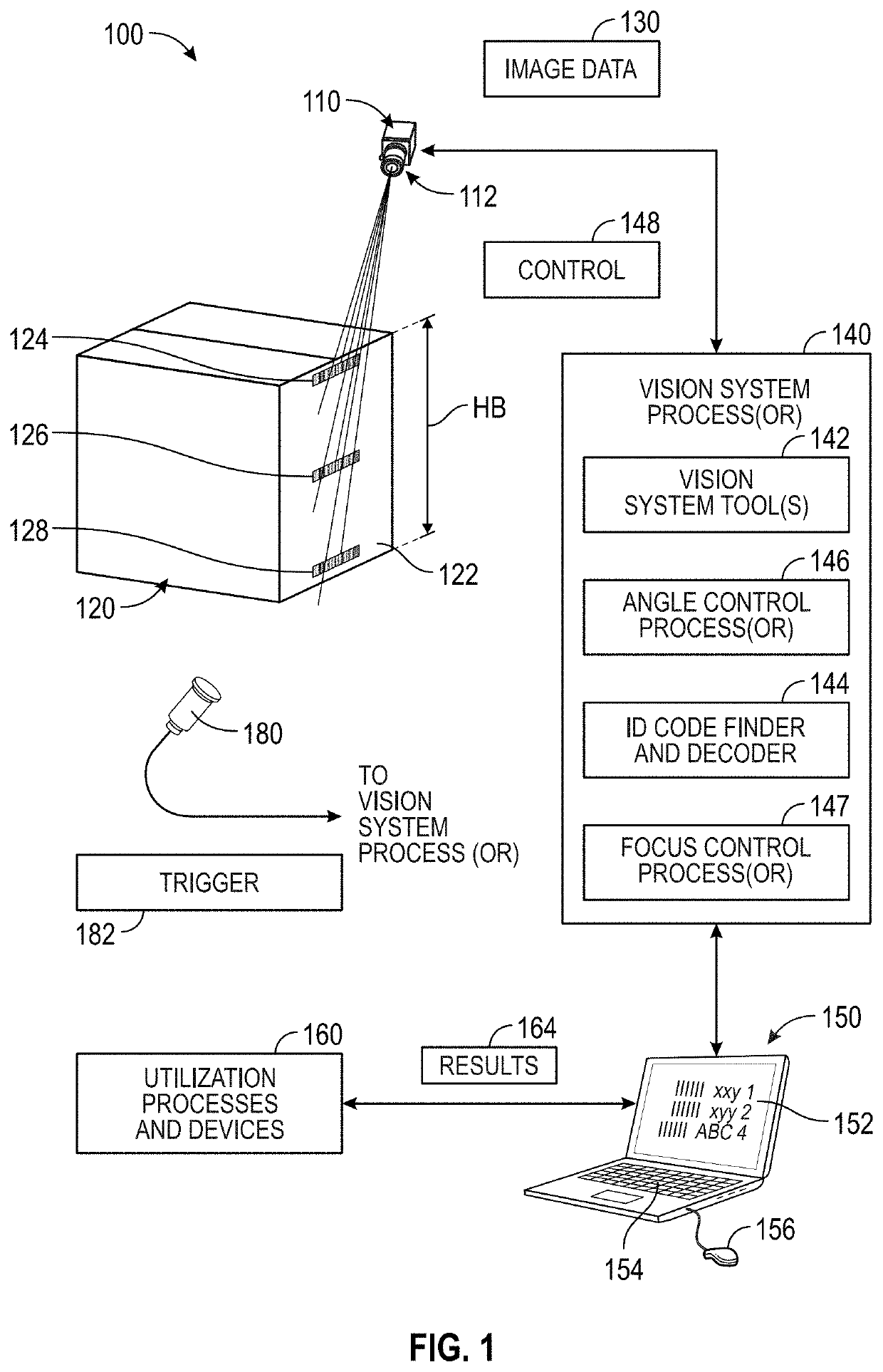
[0026]FIG. 1 shows a vision system arrangement 100 for use in providing an enhanced depth of field (DOF) useful in imaging detailed features, such as ID codes located on imaged object surfaces over a relatively large distance. The arrangement 100 includes a imaging system (also herein termed a “camera assembly”) 110 with a corresponding optics package 112 that directs received light from the surface of the depicted, exemplary object a box) 120 onto the surface of a sensor S (described below in FIG. 2). As shown, the camera assembly is directed to acquire an image of the side 122 of the box 120, where it is desired to acquire and decode various ID codes 124, 126 and 128 along the box height HB. The variation in height, in combination with the small and precise details present in the ID codes, can make the task of decoding somewhat challenging. That is, a camera with a conventional DOF may only be able to focus adequately upon one or two ID codes, but not all three c...


PUM


Abstract

This invention provides a system and method for enhanced depth of field (DOF) advantageously used in logistics applications, scanning for features and ID codes on objects. It effectively combines a vision system, a glass lens designed for on-axis and Scheimpflug configurations, a variable lens and a mechanical system to adapt the lens to the different configurations without detaching the optics. The optics can be steerable, which allows it to adjust between variable angles so as to optimize the viewing angle to optimize DOF for the object in a Scheimpflug configuration. One, or a plurality, of images can be acquired of the object at one, or differing angle settings, with the entire region of interest clearly imaged. In another implementation, the optical path can include a steerable mirror and a folding mirror overlying the region of interest, which allows different multiple images to be acquired at different locations on the object.

Description

FIELD OF THE INVENTION[0001]This invention relates to machine vision system cameras, and more particularly to cameras having automatic adjustment optical mechanisms for use in (e.g.) finding and decoding ID codes on objects.BACKGROUND OF THE INVENTION[0002]Vision systems that perform measurement, inspection, alignment of objects and / or decoding of symbology in the form of machine-readable symbols (also termed “IDs”, such as a 2D matrix symbol) are used in a wide range of applications and industries. These systems are based around the use of an image sensor, which acquires images (typically grayscale or color, and in one, two or three dimensions) of the subject or object, and processes these acquired images using an on-board or interconnected vision system processor. The processor generally includes both processing hardware and non-transitory computer-readable program instructions that perform one or more vision system processes to generate a desired output based upon the image's pro...

Claims


Application Information

Patent Timeline
IPC IPC(8): H04N5/232H04N5/225G02B3/14G02B7/00G02B7/182G02B7/02G03B13/32G03B5/06G06K7/14
CPCH04N5/232125H04N5/2254G02B3/14G02B7/003G06K7/1417G02B7/021G03B13/32G03B5/06G06K7/1413G02B7/1822G02B27/0075G06K7/10831H04N23/55H04N23/959
Inventor DORADO, JOSE FERNANDEZLOZANO, ESTHER OTEOCAMPOS, PABLO GARCIANUNNINK, LAURENS
Owner COGNEX CORPORATION
Why Eureka
Try Eureka