Wedge osteotomy device and method of use

a technology of osteotomy and limb, which is applied in the field of wedge osteotomy devices, can solve the problems of undesirable limb shortening and addition

Active Publication Date: 2020-04-16
COLORADO STATE UNIVERSITY
View PDF2 Cites 1 Cited by
  • Summary
  • Abstract
  • Description
  • Claims
  • Application Information

AI Technical Summary

Problems solved by technology

Third, the osteotomies should meet exactly at the “tip” of the wedge (i.e. a wedge is removed rather than a trapezoid piece of bone, which results in additional, undesirable limb shortening).

Method used


Image

  • Wedge osteotomy device and method of use
  • Wedge osteotomy device and method of use
  • Wedge osteotomy device and method of use

Examples


Embodiment Construction

[0040]I. Wedge Osteotomy Device

[0041]A. Overview

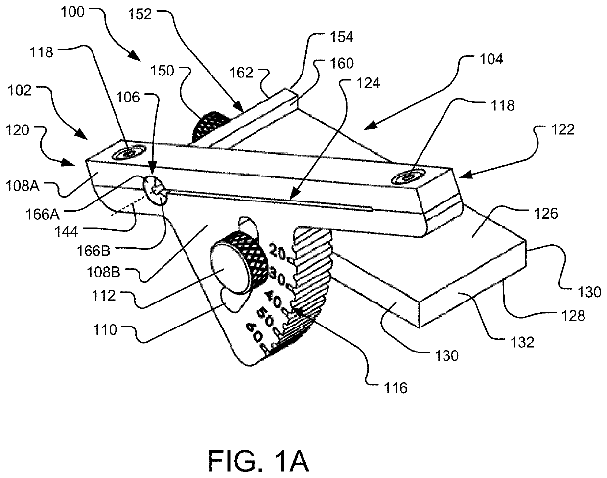
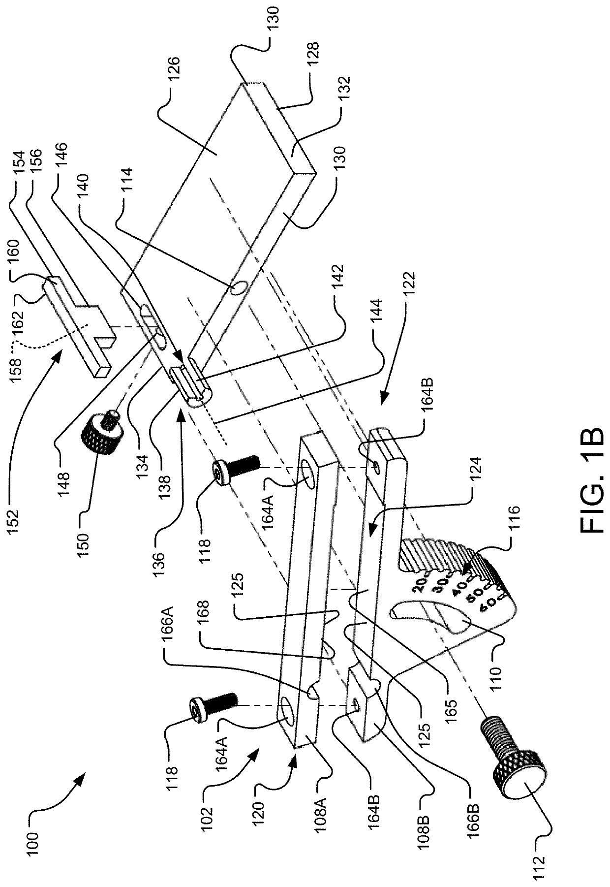
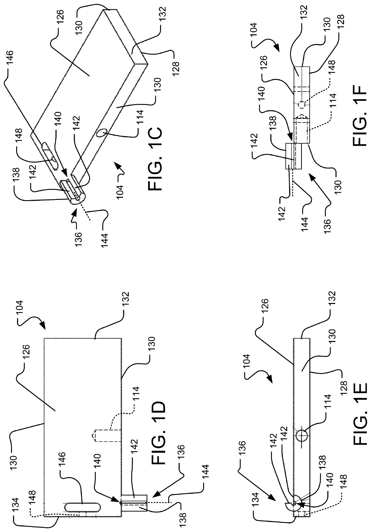
[0042]Aspects of the present disclosure involves a wedge osteotomy device 100 as seen in FIG. 1A, which shows the device in an isometric view. As seen in the figure, the device 100 may include a cutting guide 102 and a base plate 104 that are pivotally connected at a joint 106. The cutting guide 102 may include a guide body 108 that may be manufactured from a single component or multiple components. FIG. 1B, which is an isometric exploded view of the wedge osteotomy device 100, depicts an upper guide body 108A and a lower guide body 108B in a sample construction; however, the device 100 may be constructed of a single guide body 108 without departing from the teachings of the present disclosure.

[0043]As seen in FIGS. 1 A and 1B, the lower guide body 108B of the wedge osteotomy device 100 may include an arcuate slot 110 with an arc defined by a radius to the joint 106. A thumb-screw 112 may extend through the arcuate slot 110 and into a ...


PUM


Abstract

A wedge osteotomy device including a cutting guide coupled to a base plate via a joint. The cutting guide configured to pivot relative to the base plate about a pivot axis extending through the joint. The cutting guide including a guide body including a cutting slot extending through the guide body, an arcuate slot extending through the guide body and defining a radius to the joint, and a plurality of markers on the guide body identifying a position of the cutting guide relative to the base plate. The base plate including planar top and bottom surfaces.

Description

CROSS-REFERENCE TO RELATED APPLICATION[0001]This application claims the benefit of U.S. Provisional Application No. 62 / 743,992, filed Oct. 10, 2018, which is hereby incorporated by reference in its entirety into the present application.TECHNICAL FIELD[0002]Aspects of the present disclosure involve a wedge osteotomy device, and, in particular, a closing wedge osteotomy device for the correction of limb deformities and certain ligament diseases.BACKGROUND[0003]An osteotomy is a surgical procedure where a bone is cut to shorten, lengthen, straighten it, or to change its alignment for other biomechanical reasons. One particular type of osteotomy is a wedge osteotomy that can be broken down into two types: opening wedge osteotomies; and closing wedge osteotomies. An opening wedge osteotomy is where a bone is cut (e.g., via a simple transverse osteotomy) and the bone is pivoted “open”. Then, bone graft is added to the open wedge-space along with a bone plate, for example. For this procedu...

Claims


Application Information

Patent Timeline
Patent Type & Authority Applications(United States)
IPC IPC(8): A61B17/15
CPCA61B2090/0811A61B17/152A61B2090/08021A61B2090/067A61B90/10
Inventor DUERR, FELIX
Owner COLORADO STATE UNIVERSITY
Why Eureka
Try Eureka