Supercharge Your Innovation With Domain-Expert AI Agents!

Coverslipping machine

a slipper and cover technology, applied in the field of slippers, can solve the problems of damage, damage, damage, etc., and achieve the effect of reducing the risk of damag

Active Publication Date: 2020-04-16
LEICA BIOSYST NUSSLOCH
View PDF0 Cites 0 Cited by
  • Summary
  • Abstract
  • Description
  • Claims
  • Application Information

AI Technical Summary

Benefits of technology

The patent text describes a system that includes a coverslipping machine and a stainer. The system is designed to automatically transfer specimen slide magazines, which contain samples that have been coverslipped, from the coverslipping machine to the stainer. This eliminates the need for manual labor and ensures consistent and efficient processing of samples. The technical effect of this system is improved workflow efficiency and streamlined sample processing.

Problems solved by technology

It has been recognized in particular that damage can occur in particular because mounting medium dries out on or in components of the coverslipping machine, or on samples onto which a coverslip has not yet been placed.
It has furthermore been recognized that damage can occur if the coverslipping machine stops in a random and undefined operating state, especially if restarting from that state is not possible because, for example, parameter values that are required, in particular within a control software program for control purposes or in order to identify the individual samples, become lost, or if a restart is prevented for mechanical reasons.
It is also possible, disadvantageously, for damage to occur, or for the coverslipping machine to find itself in a state from which a restart is not possible, if the user attempts, by removing parts of the coverslipping machine that has halted in the undefined operating state, to gain access to samples that are being processed so as to remove them.

Method used


Image

  • Coverslipping machine
  • Coverslipping machine
  • Coverslipping machine

Examples


Embodiment Construction

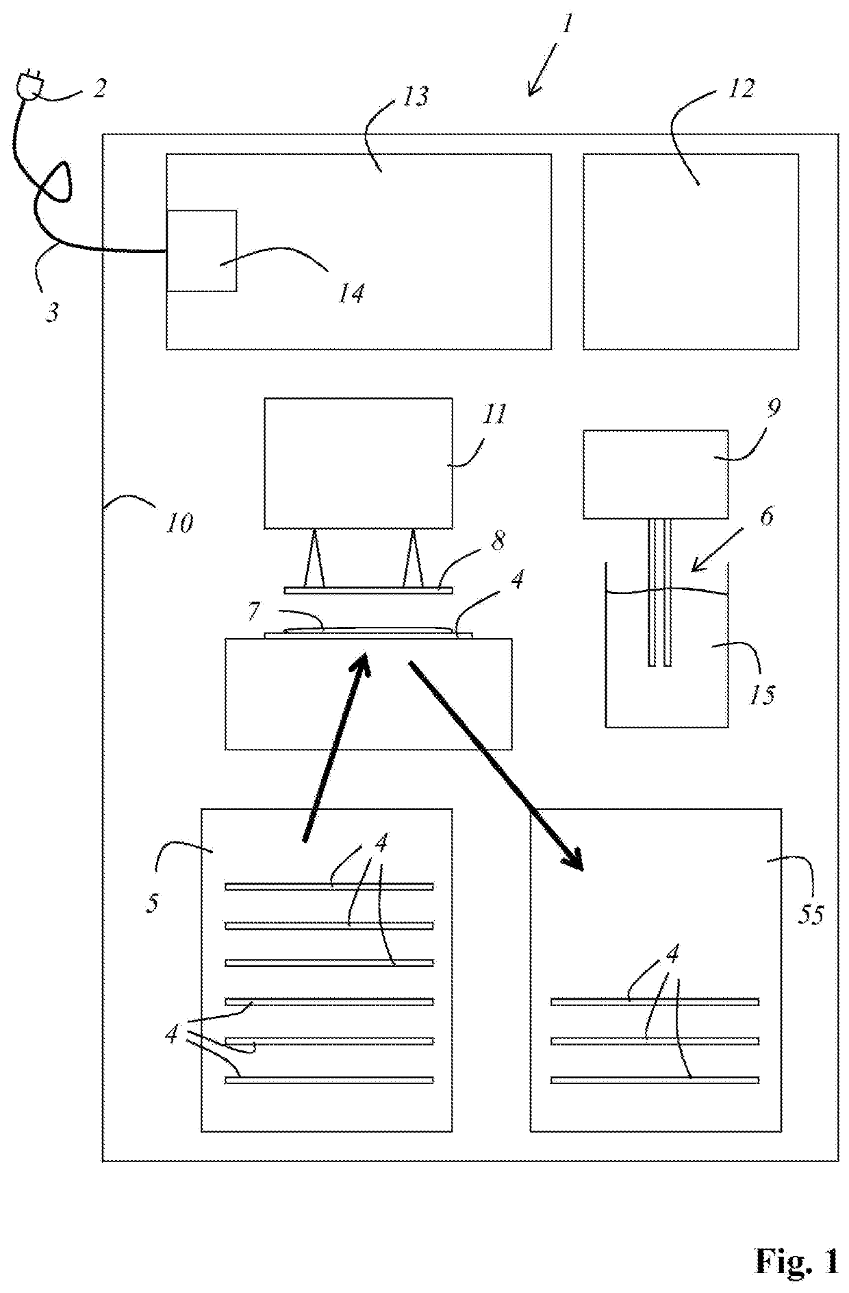
[0052]FIG. 1 shows, very schematically, an exemplifying embodiment of a coverslipping machine 1 according to the present invention. Coverslipping machine 1 comprises a power plug 2 and a connector cable 3 with which it can be connected to an electrical power grid (not depicted). Coverslipping machine 1 is embodied to remove specimen slides 4, having samples present thereon, from a specimen slide magazine 5 and deliver them to a coverslipping process in which a mounting medium 7 is applied by means of a hollow needle 6, and then a coverslip 8 is applied, onto each specimen slide 4.

[0053]Hollow needle 6 can be moved in motorizedly controlled fashion, by means of a manipulator 9, within housing 10 of coverslipping machine 1. Provision is made in particular that upon the application of mounting medium 7, hollow needle 6 is moved relative to the respective specimen slide 4 that is currently to be coverslipped, in order to distribute mounting medium 7 on specimen slide 4.

[0054]Coverslips ...


PUM

PropertyMeasurementUnit
temperatureaaaaaaaaaa
pressureaaaaaaaaaa
electrical energyaaaaaaaaaa

Abstract

A coverslipping machine (1) is embodied to be connected to an electrical power grid in order to be supplied with electrical energy as an electrical load; and removes specimen slides (4), having samples present thereon, from a specimen slide magazine (5) and respectively carries out a coverslipping process in which a mounting medium (7) and then a coverslip (8) are applied onto each specimen slide (4); and deposits the coverslipped specimen slides (4) in the specimen slide magazine (5) or in a further specimen slide magazine (55). The coverslipping machine (1) has an electrical energy reservoir (12) and an electronic control apparatus (13). The electronic control apparatus (13) detects disruptions in the supply of electrical energy from the power grid and, in the event of a disruption, switches over to a withdrawal of electrical energy from the electrical energy reservoir (12), and carries out a safety routine that includes at least the safety steps of completing the coverslipping of specimen slides (4) already equipped with the mounting medium (7), and then depositing them in the specimen slide magazine (5) or in the further specimen slide magazine (55).

Description

CROSS-REFERENCE TO RELATED APPLICATIONS[0001]The present application is the U.S. national phase of International Application No. PCT / EP2019 / 054629 filed Feb. 25, 2019, which claims priority of German Application No. 10 2018 104 709.6 filed Mar. 1, 2018, the entire disclosure of which is incorporated herein by reference.FIELD OF THE DISCLOSURE[0002]The invention relates to a coverslipping machine which is embodied to be connected to an electrical power grid in order to be supplied with electrical energy as an electrical load; and which removes specimen slides, having samples present thereon, from a specimen slide magazine and respectively carries out a coverslipping process in which a mounting medium and then a coverslip are applied onto each specimen slide; and which deposits the coverslipped specimen slides in the specimen slide magazine or in a further specimen slide magazine.BACKGROUND OF THE DISCLOSURE[0003]A number of devices are used for sample preparation in a pathology labor...

Claims


Application Information

Patent Timeline
Patent Type & Authority Applications(United States)
IPC IPC(8): G01N1/31G01N35/00
CPCG01N1/312G01N2035/00138G01N2035/00039G01N35/00712G01N35/00029
Inventor SIEHL, BENJAMINSHARPE, MARKUSWITTMANN, MARKUS
Owner LEICA BIOSYST NUSSLOCH
Features
  • R&D
  • Intellectual Property
  • Life Sciences
  • Materials
  • Tech Scout
  • Unparalleled Data Quality
  • Higher Quality Content
  • 60% Fewer Hallucinations
Learn More