Eureka AIR delivers breakthrough ideas for toughest innovation challenges, trusted by R&D personnel around the world.

Grinding mill

Active Publication Date: 2020-04-23
METSO OUTOTEC (FINLAND) OY
View PDF30 Cites 0 Cited by
  • Summary
  • Abstract
  • Description
  • Claims
  • Application Information

AI Technical Summary

Benefits of technology

The invention prevents a continuous path from being formed between the grinding mill and the oil in the bearing, even if there is a malfunction. This prevents contamination of the material to be ground. The grinding mill has the advantage of being able to prevent contamination during grinding.

Problems solved by technology

It is common with increasing mill diameters and flow rates for the discharge arrangement to restrict the performance of the mill by limiting material transfer rates and grinding efficiency.
This is due to an inability to transport the ground material through the grate and pulp lifters limiting the transfer rate due to slurry flow back / short circuiting and carry over.
The impact of this restriction in mill flow rate is a reduction in mill performance (product size) due to the resulting slurry pool which dissipates the energy of the balls / ore impacting the toe of the charge.
However, this approach has been limited to very small grinding mills, as the open ended design has not been sufficiently stiff to support a journal with discrete bearing support points with increasing mill diameters and charge loads.
Due to the volume of weld material this connection can be problematic with reliability potentially reduced by the presence of weld defects and residual stresses.
One of the problems associated with known open-ended grinding mills has, thus, been that in case of a malfunction there is a risk that oil from bearings supporting a drum of the grinding mill comes into contact with the material to be ground causing contamination of the material.

Method used


Image

  • Grinding mill
  • Grinding mill
  • Grinding mill

Examples


Embodiment Construction

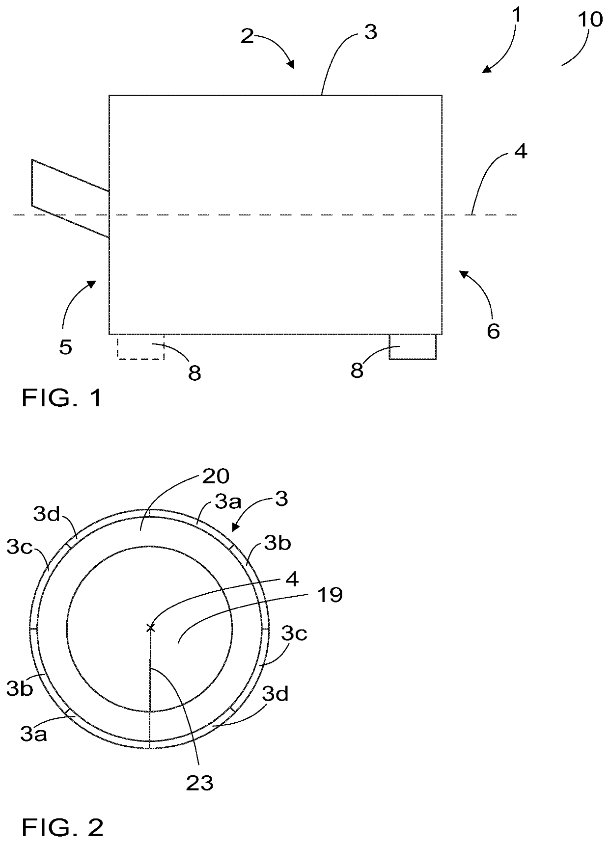
[0018]FIG. 1 is illustrates schematically a grinding mill 1. FIG. 2 illustrates schematically a grinding mill 1 seen from a second end 6, in other words the discharge end of the grinding mill. FIGS. 1 and 2 only show some features of the grinding mill 1 that help understanding the current solution. It is clear for a person skilled in the art that a grinding mill may and usually does comprise other features as well.

[0019]A grinding mill 1, such as the grinding mill of FIG. 1, comprises a drum 2 comprising a cylindrical shell 3. In a grinding mill 1 of the current solution, the longitudinal axis 4 of the drum 2 is arranged in a substantially horizontal position in a use position of the grinding mill 1. The longitudinal axis 4 of the drum refers to the axis extending along the centre line of the shell 3 from one end of the cylinder-shaped shell s to another. Horizontal position refers to the longitudinal axis 4 extending in a substantially horizontal direction. In other words, the long...


PUM


Abstract

An open-ended grinding mill (1) includes a drum (2) including a cylindrical shell (3), wherein the longitudinal axis (4) of the drum is arranged in a substantially horizontal position in a use position of the grinding mill (1). The drum (2) includes a first end (5) at the feed end of the shell and a second end (6) at the discharge end of the shell. The grinding mill further includes a bearing (8) supporting the drum at the second end, and a support structure (9) to connect the drum (2) to the bearing (8). The support structure is configured to provide a wall external to the shell, whereby the shell and the support structure provide a double-wall structure separating the bearing from the inside of the drum.

Description

BACKGROUND[0001]The invention relates to grinding mills, and more particularly to open-ended grinding mills.[0002]Grinding mills, specifically semi autogenous and autogenous mills, rely on their ability to generate impact breakage of the ore charge and transport the ground material through the discharge pulp lifters out of the mill. It is common with increasing mill diameters and flow rates for the discharge arrangement to restrict the performance of the mill by limiting material transfer rates and grinding efficiency. This is due to an inability to transport the ground material through the grate and pulp lifters limiting the transfer rate due to slurry flow back / short circuiting and carry over. The impact of this restriction in mill flow rate is a reduction in mill performance (product size) due to the resulting slurry pool which dissipates the energy of the balls / ore impacting the toe of the charge.[0003]While open ended mills can provide a solution to this problem removing the ne...

Claims


Application Information

Patent Timeline
IPC IPC(8): B02C17/18B02C17/04
CPCB02C17/183B02C17/04B02C17/181
Inventor GREEN, NICHOLASBERGER, BRIANBORDI, DAMONWINTHER, KJELLHOLSHAGEN, BJOERN
Owner METSO OUTOTEC (FINLAND) OY
Why Eureka
Eureka Blog
Learn More