Latch Guiding And Coupling Device

a technology of coupling device and latch, which is applied in the direction of building locks, door/window fittings, constructions, etc., can solve the problems of easy deviation of latch, difficult or even impossible entry of latch, and uneven latch between latching and unlatching positions, etc., to achieve easy and pivotable mounting, easy maintenance or replacement, and easy assembly and maintenance

Inactive Publication Date: 2020-04-30
I TEK METAL MFG
View PDF0 Cites 0 Cited by
  • Summary
  • Abstract
  • Description
  • Claims
  • Application Information

AI Technical Summary

Benefits of technology

[0005]Since the first side of the coupling seat includes the recessed portion having two ends with positioning grooves extending to the first surface to form notches, the two ends of the axle can easily be inserted into the positioning grooves via the notches. Furthermore, the stopper portions of the locking plate cover the notches, such that the roller can be easily and pivotably mounted in the recessed portion of the coupling seat, achieving assembly of the latch guiding and coupling device. For maintenance operation of the latch guiding and coupling device, the roller can be easily maintained or replaced after removal of the locking plate. Thus, the latch guiding and coupling device according to the present invention can be easily assembled and maintained.

Problems solved by technology

After long-term use, the latch is liable to deviate, and the movement of the latch between the latching and unlatching positions is not smooth, such that the latch is difficult to or even cannot enter the insertion groove.
As a result, the door cannot be closed.
However, an axle of the roller extends through the coupling seat and the roller and has two ends fixed in the coupling seat, leading to difficulties in assembly and maintenance.
In some cases, the roller cannot be detached, such that the whole latch guiding and coupling device must be replaced.

Method used


Image

  • Latch Guiding And Coupling Device
  • Latch Guiding And Coupling Device
  • Latch Guiding And Coupling Device

Examples


Embodiment Construction

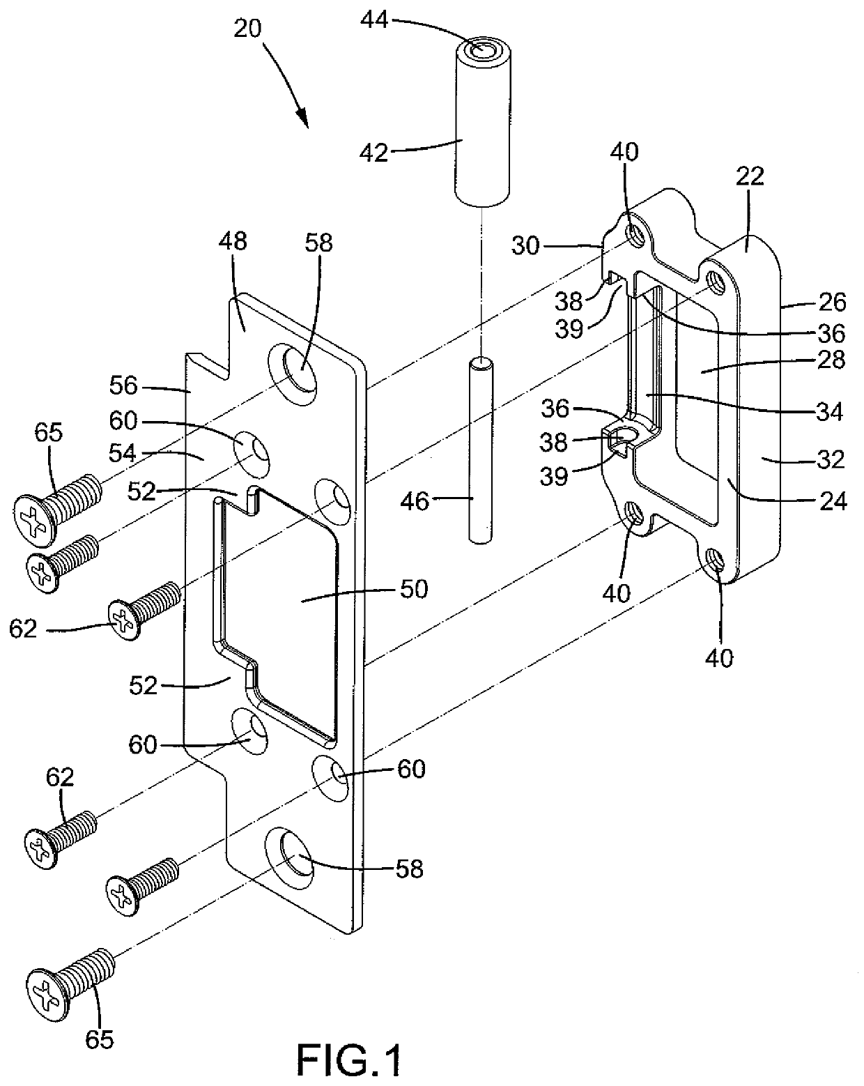
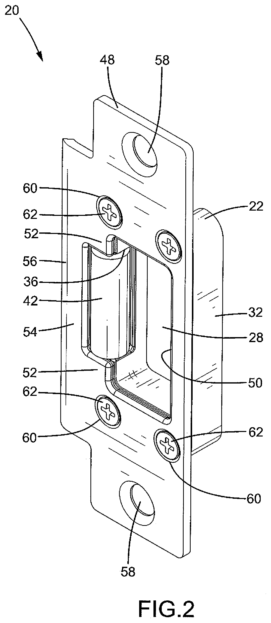
[0017]With reference to FIGS. 1 and 2, a latch guiding and coupling device 20 according to the present invention includes a coupling seat 22 having a first surface 24 and a second surface 26 spaced from the first surface 24. The coupling seat 20 further includes first and second sides 30 and 32 between the first surface 24 and the second surface 26. An insertion groove 28 is defined between the first side 30 and the second side 32. The insertion groove 28 extends from the first surface 24 through the second surface 26. A recessed portion 34 is formed in the first side 30 and includes two ends. Each of the two ends of the recessed portion 34 includes a lateral wall 36 having a positioning groove 38. Each positioning groove 38 extends to the first surface 24 to form a notch 39. A plurality of fixing holes 40 is defined in the first surface 24 of the coupling seat 22. Each of the plurality of fixing holes 40 can be a thread-free bore or has an inner threading.

[0018]With reference to FI...


PUM


Abstract

A latch guiding and coupling device includes a coupling seat having first and second sides. An insertion groove is defined between the first and second sides and extends from a first surface through a second surface of the coupling seat. A recessed portion is formed in the first side and rotatably receives a roller. Each of two ends of the recessed portion has a positioning groove extending to the first surface to form a notch. An axle extends through the roller and includes two ends respectively received in the positioning grooves. A locking plate is mounted to the first surface of the coupling seat. The locking plate includes an opening aligned with the insertion groove and two stopper portions aligned with the positioning grooves. Each stopper portion covers one of the notches to prevent the axle from disengaging from the positioning grooves. The roller protrudes beyond the locking plate.

Description

BACKGROUND OF THE INVENTION[0001]The present invention relates to a latch guiding and coupling device and, more particularly, to a latch guiding and coupling device that is mounted to a side of a door frame and that can be easily assembled and maintained.[0002]A typical door lock device generally includes a latch guiding and coupling device mounted to a side of a door frame and a latching unit mounted to a door. The latch guiding and coupling device includes a coupling seat and a locking plate extending from the coupling seat. A guiding plate extends from a side of the locking plate. An insertion groove is recessed in the coupling seat. When the latching unit on the door is misaligned from the latch guiding and coupling device, the door is in an open state. On the other hand, when the latching unit on the door is aligned with the latch guiding and coupling device, the door is aligned with the door frame and is in a closed state. During closing of the door, a latch of the latching un...

Claims


Application Information

Patent Timeline
Patent Type & Authority Applications(United States)
IPC IPC(8): E05B15/02
CPCE05Y2900/132E05B15/0205E05B15/022E05B17/007
Inventor TIEN, HUNG-JEN
Owner I TEK METAL MFG
Why Eureka
Try Eureka