
Enhanced printed circuit board monopole antenna

a printed circuit board and antenna technology, applied in the field of antennas, can solve the problems of reducing the reception and transmitting performance of the antenna, and achieve the effect of increasing the radiation efficiency of the antenna

Active Publication Date: 2020-04-30
POWER WAVE ELECTRONICS
View PDF0 Cites 0 Cited by
  • Summary
  • Abstract
  • Description
  • Claims
  • Application Information

AI Technical Summary

Benefits of technology

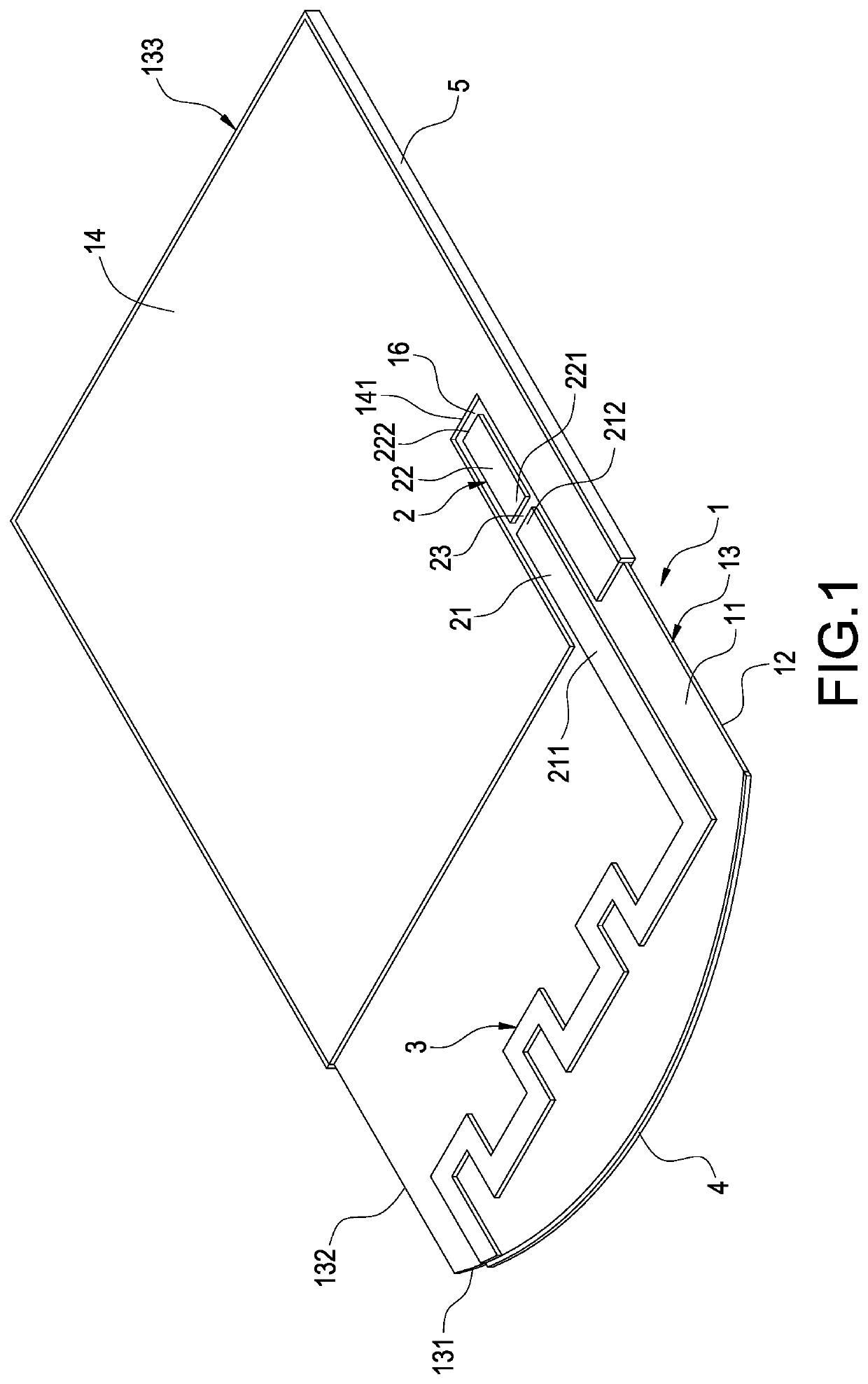
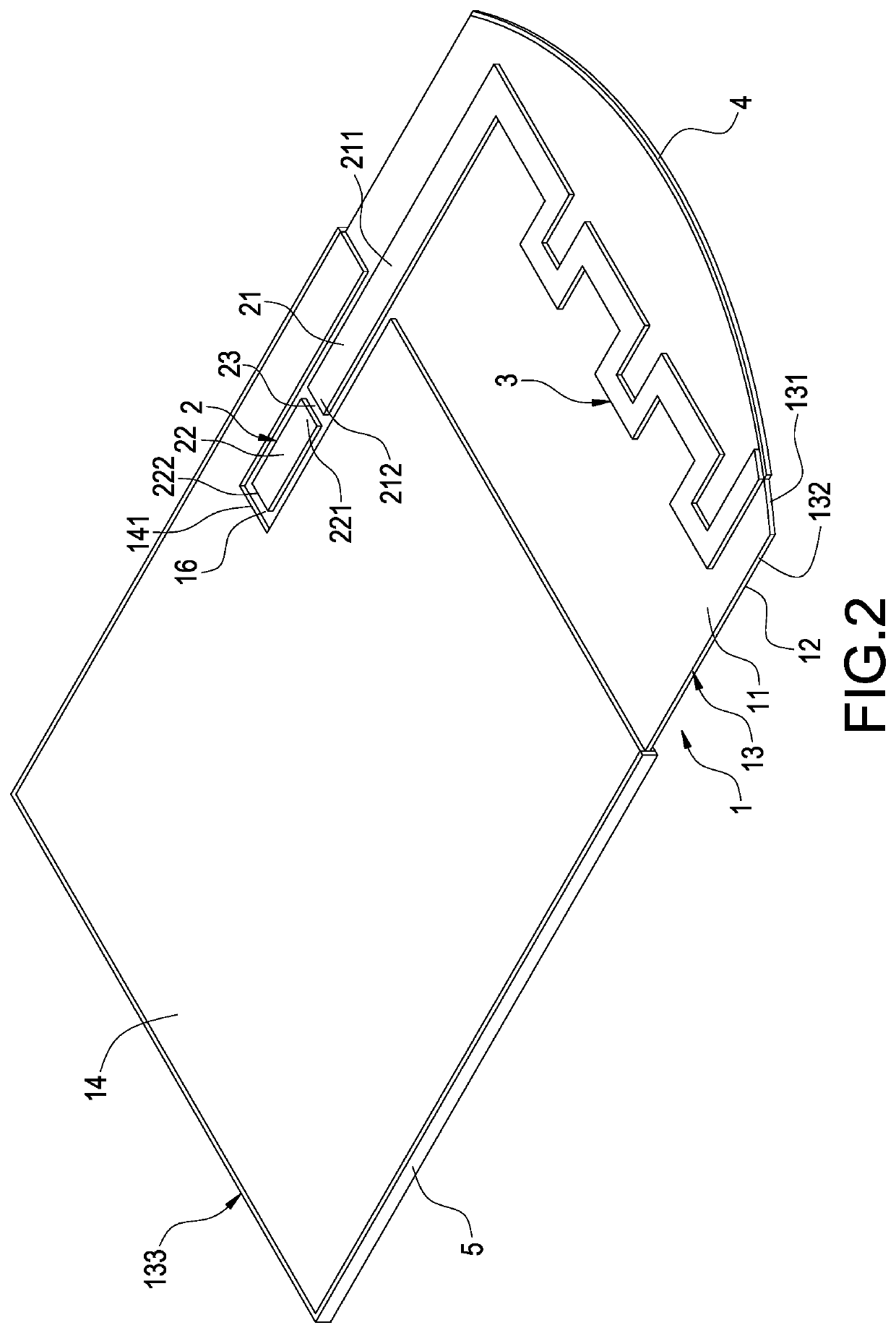
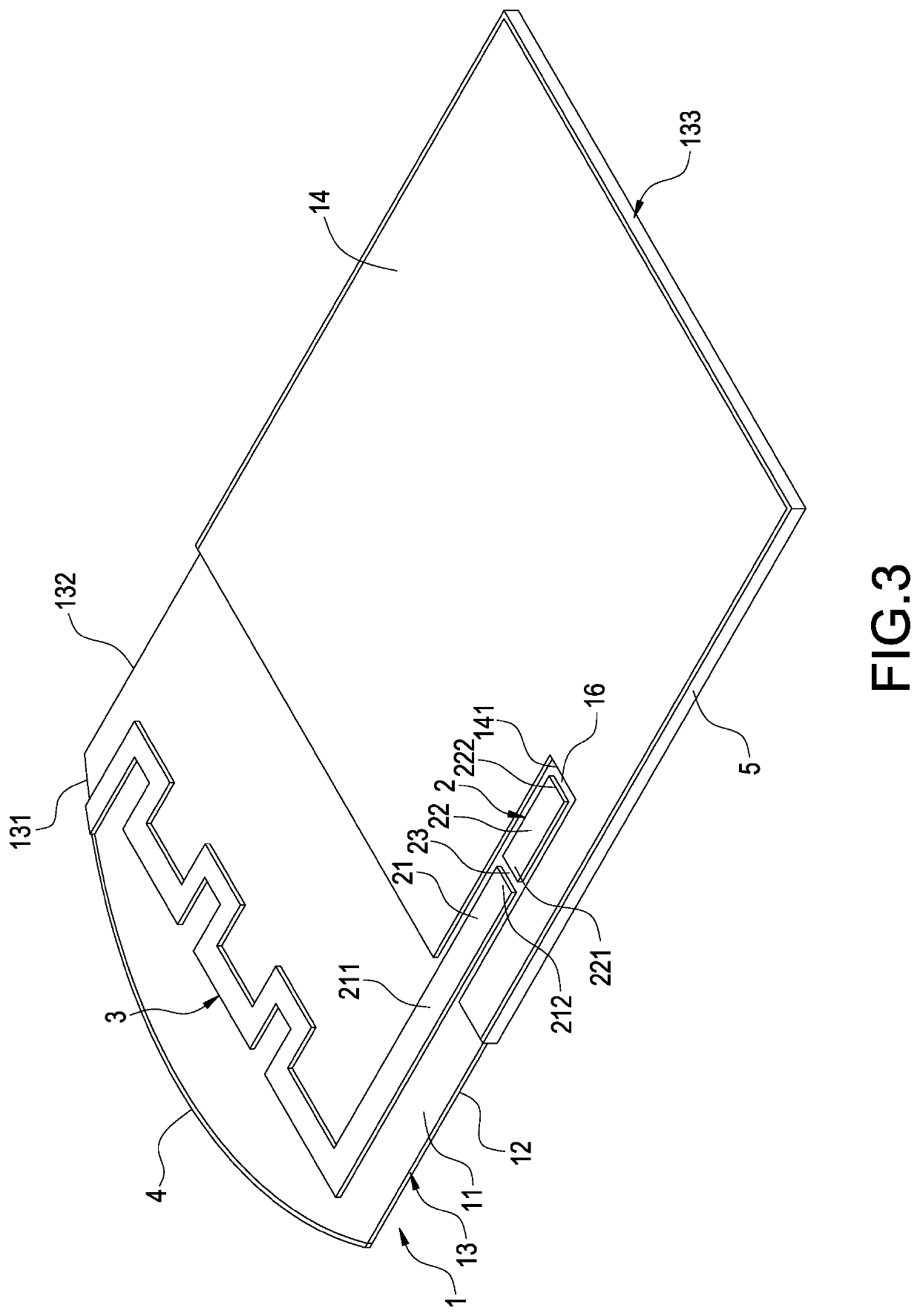
The present invention provides a new enhanced printed circuit board monopole antenna that can adjust the impedance, resonant frequency, bandwidth, and radiation effect to control the frequency range from 88 MHZ to 60 GHZ. This is achieved by cooperation between a first-radiation unit and a second-radiation unit, which forms a frequency wave length at a specific ratio. The antenna can effectively increase its radiation efficiency.

Problems solved by technology

But if the volume of the antenna is reduced, the receiving and transmitting performance of the antenna may be decreased, so that the action-style electronic apparatus cannot perform the data transmission with another electronic apparatus or another action-style electronic apparatus.

Method used


Image

  • Enhanced printed circuit board monopole antenna
  • Enhanced printed circuit board monopole antenna
  • Enhanced printed circuit board monopole antenna

Examples


first embodiment

[0056]FIG. 8 shows a curve diagram of the reflection coefficient testing of the enhanced printed circuit board monopole antenna with the second-radiation unit at high frequencies of the present invention. Please refer to FIGS. 1˜5 at the same time. As shown in FIG. 8, when the enhanced printed circuit board monopole antenna with the second-radiation unit 4 is used, at frequency 2.400 GHZ is −13.439 dB, at frequency 2.450 GHZ is −20.936 dB, at frequency 2.483 GHZ is −11.216 dB and at frequency 2.4436250 GHZ is −32.105 dB. Therefore, according to the frequency wave length (1λ, ½λ, ¼λ or ⅛λ) formed by the first-radiation unit 3 and the second-radiation unit 4 cooperating with each other, the present invention controls 88 MHZ-60 GHZ frequency range to achieve the predetermined target impedance, resonant frequency, bandwidth and radiation efficiency. The antenna radiation efficiency can be increased effectively.

[0057]FIG. 6 shows the enhanced printed circuit board monopole antenna withou...

second embodiment

[0063]FIG. 16 shows a curve diagram of the reflection coefficient testing of the enhanced printed circuit board monopole antenna with the second-radiation unit at low frequencies of the present invention. Please refer to FIG. 11 at the same time. As shown in FIG. 16, when the enhanced printed circuit board monopole antenna with the second-radiation unit 4 is used, at frequency 300.00000 MHZ is −12.218 dB, at frequency 315.00000 MHZ is −24.314 dB, at frequency 330.00000 MHZ is −10.748 dB and at frequency 313.00000 MHZ is −28.078 dB. Therefore, according to the frequency wave length (1λ, ½λ, ¼λ or ⅛λ) formed by the first-radiation unit 3 and the second-radiation unit 4 cooperating with each other, the present invention controls 88 MHZ-60 GHZ frequency range to achieve the predetermined target impedance, resonant frequency, bandwidth and radiation efficiency. The antenna radiation efficiency can be increased effectively.

[0064]FIG. 17 shows a front view of the enhanced printed circuit b...


PUM


Abstract

An enhanced printed circuit board monopole antenna includes a baseplate, a signal feed-in unit, a first-radiation unit, a second-radiation unit and an auxiliary ground unit. The first-radiation unit and the second-radiation unit are arranged on a front side and an edge side of the baseplate. The auxiliary ground unit is arranged on the edge side and electrically connected to a first ground unit and a second ground unit on the baseplate. Adjusting the first-radiation unit controls 88 MHZ-60 GHZ frequency range impedance, resonant frequency, bandwidth and radiation effect. According to the frequency wave length (1λ, ½λ, ¼λ or ⅛λ) formed by the first-radiation unit and the second-radiation unit cooperating with each other, controlling 88 MHZ-60 GHZ frequency range achieves the predetermined target impedance, resonant frequency, bandwidth and radiation efficiency. The antenna radiation efficiency can be increased effectively.

Description

CROSS-REFERENCE TO RELATED APPLICATION[0001]This application is a divisional application of U.S. patent application Ser. No. 15 / 614,593, filed on Jun. 5, 2017, and entitled “ENHANCED PRINTED CIRCUIT BOARD MONOPOLE ANTENNA”. The entire disclosures of the above application are all incorporated herein by reference.BACKGROUND OF THE INVENTIONField of the Invention[0002]The present invention relates to an antenna, and especially relates to an enhanced printed circuit board monopole antenna which is used for data transmission.Description of the Related Art[0003]It is well known that the Bluetooth and WIFI system are arranged in the existing action-style electronic apparatus, so that the action-style electronic apparatus can perform the data transmission with another electronic apparatus or another action-style electronic apparatus.[0004]With the continuous progress of the modern science and technology, a lot of action-style electronic apparatuses are slim and compact (for examples, the ea...

Claims


Application Information

Patent Timeline
Patent Type & Authority Applications(United States)
IPC IPC(8): H01Q5/357H01Q1/24H01Q1/38H01Q9/42
CPCH01Q1/243H01Q5/357H01Q9/42H01Q1/38
Inventor LIAO, WEN-JIAOTSAI, WEI-HONGTSAI, YUN-CHAN
Owner POWER WAVE ELECTRONICS
Learn More