
Process and apparatus for cooking utilizing nebulized water particles and air

a technology of nebulized water particles and cooking process, which is applied in the field of ovens, can solve the problems of affecting the appearance of cooked food, the use of dry heat ovens, and the loss of nutritional elements and vitamins

Active Publication Date: 2020-05-07
AHA LLC
View PDF0 Cites 10 Cited by
  • Summary
  • Abstract
  • Description
  • Claims
  • Application Information

AI Technical Summary

Benefits of technology

This patent is about a process for refrigerating an oven. The process involves using a reservoir to chill water, which is then sent to a nebulizer. Compressed air is also chilled and then combined with the chilled water. This combination of air and water is then forced into the cooking chamber of the oven to quickly cool the chamber. The technical effect is to provide a more efficient way to cool the oven and improve cooking results.

Problems solved by technology

Although commonly used, there are many problems associated with the use of dry heat ovens.
For example, the cooked food usually has a deteriorated appearance, loss of nutritional elements and vitamins, and substantial shrinkage due to the significant loss of water content that occurs with heating the food with dry heat.
Accordingly, dry heat ovens are not efficient because excess heat is needed to compensate for the necessary and substantial loss of moisture from the food.
However, there are also many problems associated with the use of water vapor ovens.
For example, the large volume of water used during the cooking cycle often becomes contaminated with albumin, fat and other effluents that exude from the food as it is cooked.
As a result, a large volume of contaminated water must be drained from the bottom of the unit.
However, there are drawbacks with steam ovens.
This “sweat” often collects, pools and runs over the sides of cooking pans, resulting in a hard to clean food film on the oven's interior surface.
Furthermore, the high steam temperatures have a greatly deleterious effect on the nutritional value of foods cooked and are inherently dangerous as scalding and burning is necessarily imparted upon the users by water vapor heated above 212 degrees Fahrenheit.

Method used


Image

  • Process and apparatus for cooking utilizing nebulized water particles and air
  • Process and apparatus for cooking utilizing nebulized water particles and air
  • Process and apparatus for cooking utilizing nebulized water particles and air

Examples


first embodiment

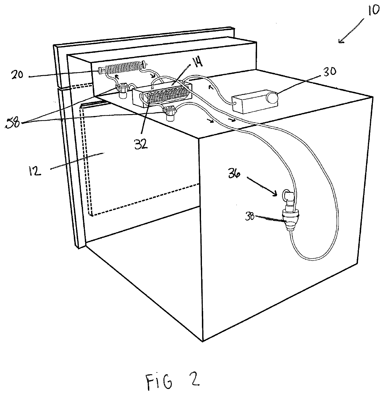
[0025]In the first embodiment shown in FIG. 2, after or as the water in the reservoir (14) is recirculating through the water heater coil (20), air is transferred through an air heater coil (32) that is submerged within the water of the reservoir. In this embodiment, the air is piped through the air heater coil, but other embodiments include alternative means of transferring the air, such as a pump. When the water in the reservoir is heated to the desired end point temperature, the air heater coil, which is made of a heat inducting material, such as copper, necessarily heats to the specific desired end temperature of the water in the reservoir. In this embodiment, the air heater comprises a coil, which is beneficial as it heats the air most efficiently when run through the coil. However, the air heater can be any shape or form and made of any material. Accordingly, when air is piped through the air heater coil, the air is heated to the desired end temperature initially selected by a...

second embodiment

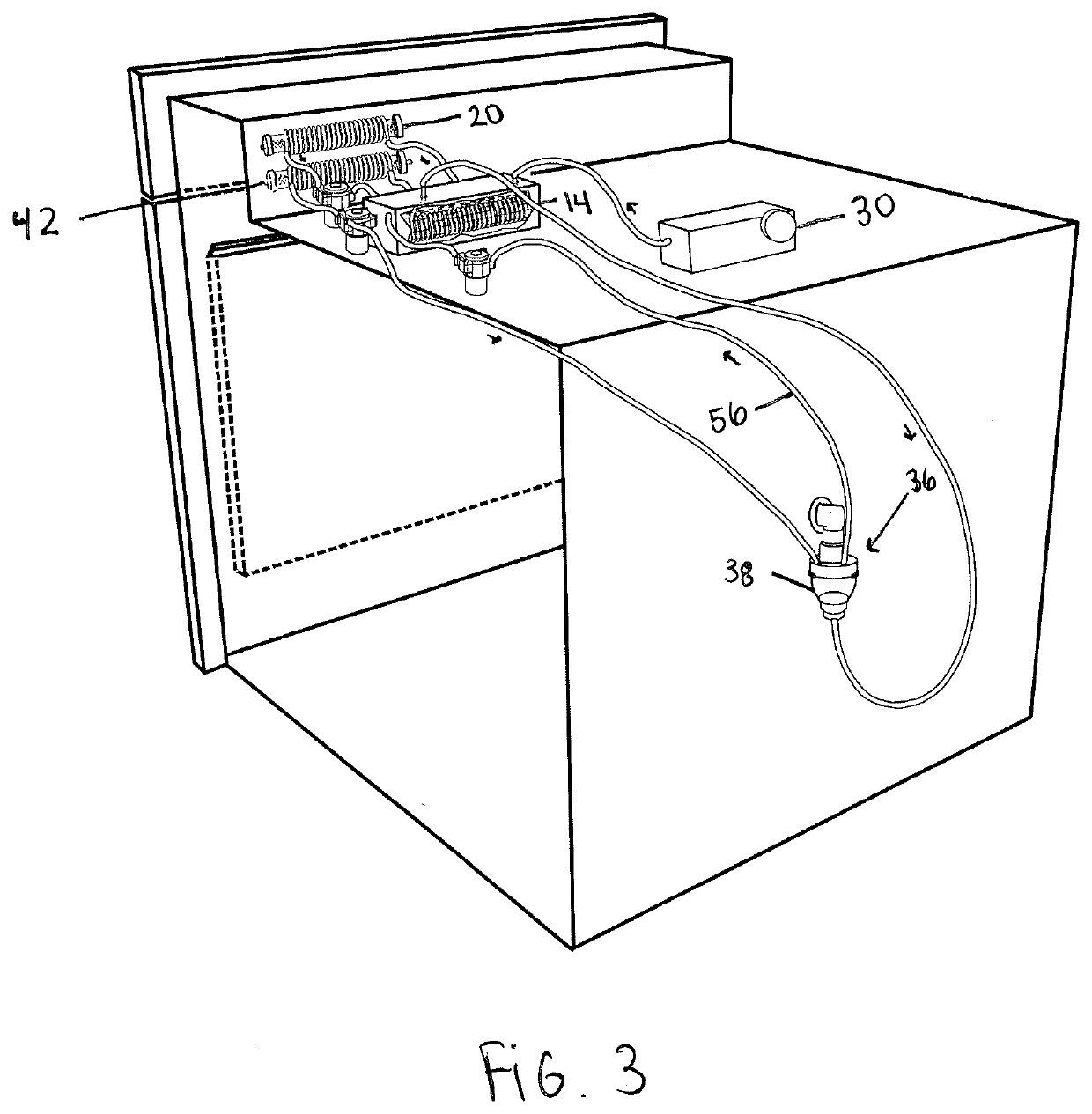
[0028]In the oven (10), as shown in FIG. 3, the heated water from the reservoir (14) is pumped through an additional water heater coil (42) on its way to the nebulizer (36). This additional water heater coil can act as a secondary heat source for the heated water to ensure that the heated water reaches the nebulizer at the desired end temperature. The second water heater coil also ensures that the heated water has not lost its temperature as a result of its movement to the nebulizer (36). The second water heater is used as a “trimming” heater, fine-tuning the temperature of the pre-heated water in the reservoir.

[0029]In the first embodiment, as shown in FIG. 2, the heated water is nebulized into heated water particles within the nebulizer (36) using conventional nebulizer techniques. The nebulizer can be any form of nebulizer, such as a Philips Respironics HS 860 SideStream nebulizer, which are disposable and made of a plastic. These nebulizers have a unique five-hole design and a v...

third embodiment

[0035]In a third embodiment, as shown in FIG. 4, the oven (10) includes a chilling or refrigeration element, wherein either independently, or in addition to heated air and heated water being pumped to the nebulizer (36), chilled air and water is delivered to the nebulizer. In this embodiment, the air is piped through the air heater coil, but other embodiments include alternative means of transferring the air, such as a pump.

[0036]In this third embodiment, as shown in FIG. 4, there is a chilled reservoir (60) that is located outside a cooking chamber (12) of the oven (10). This chilled reservoir contains water that is pumped into the chilled reservoir at a set temperature, for instance from a cold-water tank. If the water is manually inserted or pumped from a municipal water source into the chilled reservoir, a Peltier thermoelectric block (70) is located underneath the chilled reservoir. For the refrigeration embodiment, in order to meet USDA food safety guidelines, the water temper...


PUM


Abstract

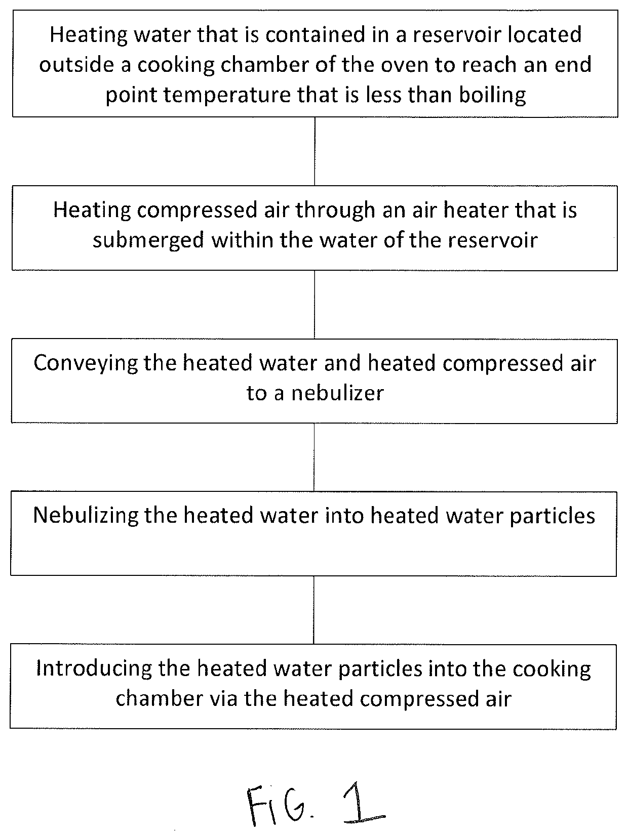
A process and apparatus for heating an oven using nebulized water particles and compressed air including the steps of heating water contained in reservoir that is located outside of a cooking chamber by transferring water within the reservoir through a water heater to reach a desired end point temperature that is less than boiling, heating compressed air by sending compressed air through an air heater that is submerged within the water of the reservoir, conveying the heated water and the heated compressed air to a nebulizer, nebulizing the heated water into heated water particles and introducing the heated water particles into the cooking chamber via the heated compressed air.

Description

CROSS-REFERENCE TO RELATED APPLICATION[0001]This application claims benefit of Provisional Application No. 62 / 649,677, filed on Mar. 29, 2018.FIELD OF THE INVENTION[0002]The field of ovens, and more particularly, to an oven utilizing nebulized water particles and air to cook food at a desired end temperatureBACKGROUND[0003]Numerous preparation devices and procedures are known for the preparation of foods including several types of ovens and similar equipment. One example of a known preparation device is a dry heat oven, as disclosed in U.S. Pat. No. 2,931,882. Although commonly used, there are many problems associated with the use of dry heat ovens. For example, the cooked food usually has a deteriorated appearance, loss of nutritional elements and vitamins, and substantial shrinkage due to the significant loss of water content that occurs with heating the food with dry heat. Accordingly, dry heat ovens are not efficient because excess heat is needed to compensate for the necessary ...

Claims


Application Information

Patent Timeline
IPC IPC(8): A21B1/36A21B1/26A23L5/10A47J27/04
CPCA47J27/04A21B1/36F24C15/327A47J2027/043A23L5/13A21B1/26F24C15/003A21B3/04F24C13/00F25B21/02F25D31/005A47J37/01
Inventor HOERTER, ROBERT
Owner AHA LLC
Learn More