Unlock instant, AI-driven research and patent intelligence for your innovation.

Cooling of gas turbine engine accessories

a technology of gas turbine engines and accessories, which is applied in the direction of machines/engines, efficient propulsion technologies, mechanical apparatuses, etc., can solve the problems of increasing weight and drag, increasing the overall diameter of the nacelle, and adversely affecting specific fuel consumption

Active Publication Date: 2020-05-07
ROLLS ROYCE PLC
View PDF0 Cites 4 Cited by
  • Summary
  • Abstract
  • Description
  • Claims
  • Application Information

AI Technical Summary

Benefits of technology

The present disclosure is about a new way to cool turbofan engines by using the bypass airflow through the engine's duct. In high bypass ratio engines, a low fan pressure ratio reduces the pressure difference across ventilation holes, limiting the amount of cooling flow that can be diverted to cool the gearbox. To solve this problem, the patent proposes to increase the pressure of the cooling flow and direct it to where it is needed using the exhaust holes of the manifold. This would allow sufficient cooling of the engine accessories even at low engine power conditions. The patent also describes the use of ventilation inlets that convert the bypass airflow into a pressure rise and a control unit to regulate the amount of cooling flow collected by the manifold. This would allow for adaptable cooling flow based on different flight conditions, reducing losses and improving engine efficiency. Additionally, the patent introduces a new design featuring a keel beam that allows for improved sealing between the core engine and the bypass zone, thereby enhancing fire zone boundary performance between the core engine and the bypass duct.

Problems solved by technology

Although effective in that the gearbox is kept away from the hot environment of the engine core, the location of the gearbox within the outer nacelle is disadvantageous in that it requires a relatively significant amount of space within the nacelle, which can increase the overall diameter of the nacelle, leading to weight and drag increase and adverse specific fuel consumption.
However, the high temperature environment near the engine core can produce thermal loads which can reduce component reliability.
However, in high bypass ratio engines, particularly at low engine power conditions, a low fan pressure ratio reduces the pressure difference across the ventilation holes and thereby limits the amount of the bypass flow that can be diverted in this way to cool the gearbox.
This in turn limits the capability of the ventilation system.
In contrast, simple ventilation holes formed in the aerodynamic cowl would not allow the amount of cooling flow to be adapted in this way so that, for example, holes sized for the maximum power take-off condition where the engine core operating temperatures are at their highest would tend to provide larger than necessary ventilation flows at engine cruise, negatively impacting the performance of the engine and increasing the engine specific fuel consumption.

Method used


Image

  • Cooling of gas turbine engine accessories
  • Cooling of gas turbine engine accessories
  • Cooling of gas turbine engine accessories

Examples


Embodiment Construction

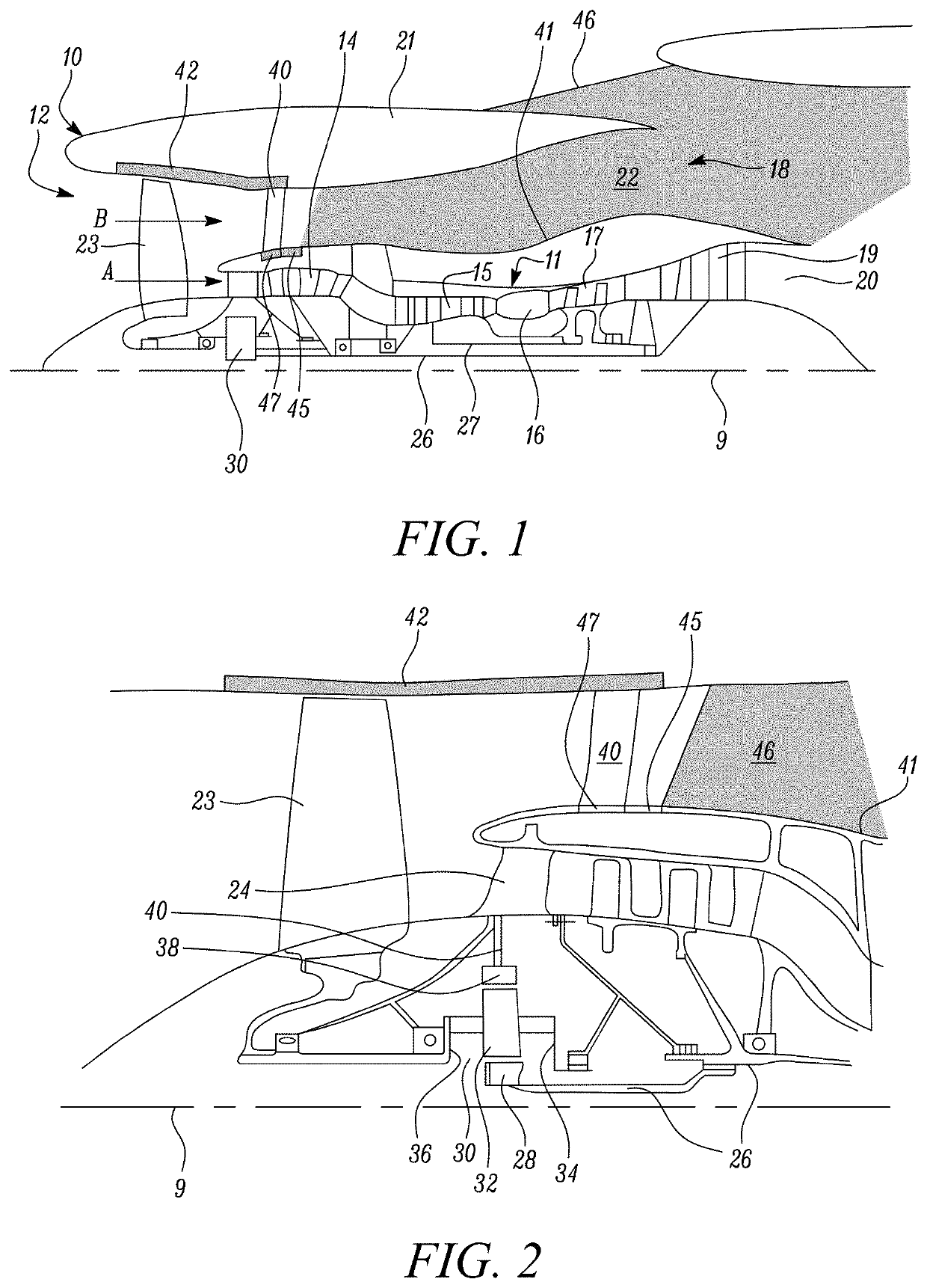
[0066]FIG. 1 illustrates a gas turbine engine 10 having a principal rotational axis 9. The engine is mounted to an airframe, e.g. under a wing, by a mounting pylon 46. The engine 10 comprises an air intake 12 and a propulsive fan 23 that generates two airflows: a core airflow A and a bypass airflow B. The gas turbine engine 10 comprises a core 11 that receives the core airflow A. The engine core 11 comprises, in axial flow series, a low pressure compressor 14, a high-pressure compressor 15, combustion equipment 16, a high-pressure turbine 17, a low pressure turbine 19 and a core exhaust nozzle 20. A nacelle 21 surrounds the gas turbine engine 10 and defines a bypass duct 22 and a bypass exhaust nozzle 18. The pylon 46 forms a bifurcation in the bypass duct where it traverses the duct to join to the engine core 11. The bypass airflow B flows through the bypass duct 22, where it is straightened by a row of outer guide vanes 40 before exiting the bypass exhaust nozzle 18. Rearward of t...


PUM


Abstract

A gas turbine engine for an aircraft is provided. The engine includes an engine core comprising a turbine, a compressor, and a core shaft connecting the turbine to the compressor. The engine further includes core casings surrounding the engine core. The engine further includes an aerodynamic cowl which surrounds the core casings. The engine further includes a propulsive fan located upstream of the engine core, the fan generating a core airflow which enters the core engine and a bypass airflow which enters a bypass duct surrounding the aerodynamic cowl. The engine further includes one or more engine accessories mounted in a space between the core casings and the aerodynamic cowl.

Description

CROSS-REFERENCE TO RELATED APPLICATIONS[0001]This application is based upon and claims the benefit of priority from United Kingdom Patent Application No. GB 1817842.6, filed on 1 Nov. 2018, which is hereby incorporated herein in its entirety.BACKGROUNDTechnical Field[0002]The present disclosure relates to cooling of engine accessories of a gas turbine engine.Description of the Related Art[0003]Conventionally the accessory gearbox of an aircraft gas turbine engine is mounted within the outer engine nacelle in a location beneath the engine. The gearbox is connected to the engine core by a radial drive shaft. The gearbox provides power to other accessories such as an auxiliary generator and pumps for hydraulic fluid, fuel, oil etc.[0004]Although effective in that the gearbox is kept away from the hot environment of the engine core, the location of the gearbox within the outer nacelle is disadvantageous in that it requires a relatively significant amount of space within the nacelle, whi...

Claims


Application Information

Patent Timeline
Patent Type & Authority Applications(United States)
IPC IPC(8): F01D25/14F02C7/12F02C7/32F02K3/06
CPCF02C7/12F02C7/32F05D2260/201F01D25/14F05D2260/606F05D2240/14F02K3/06F02C7/18F05D2220/323Y02T50/60
Inventor RAYA, EMILEINGLEY, LUCIANHUSSAIN, ZAHID M.
Owner ROLLS ROYCE PLC