Condenser for low-beam vehicle light module

Active Publication Date: 2020-05-07
H A AUTOMOTIVE SYST INC
View PDF2 Cites 1 Cited by
  • Summary
  • Abstract
  • Description
  • Claims
  • Application Information

AI Technical Summary

Benefits of technology

This patent describes a way to reduce the brightness of a specific part of a lighting system. The system uses a structure called the SEG10 luminance reducing structure, which is placed at the bottom of the condenser. This structure is designed to prevent the brightness of the lighting system from being too high, while also providing a more stable and legal allowance for the luminance of the point HV. Another addition, the patent describes a way to achieve a lower and more stable luminance for the point HV, which is important for legal judgments. Overall, the patent describes ways to improve the performance and safety of the lighting system.

Problems solved by technology

In order to form a low-beam light shape conforming to specific laws and regulations such as ECE R123 Class C, V and E, parts such as light shields have to be adopted, resulting in the defect of complex structure.
In order to conform to specific laws and regulations, the existing vehicle light modules have to be provided with tens of LED light sources, and part of the LEDs are controlled to be turned on or off to change the luminance of a specific zone in the low-beam light shape, which results in a high cost and large space of the existing vehicle light modules due to the great number of LEDs.
The existing vehicle light modules with condensers are low in integration level, light shields are still used to form cut-off lines and to reduce the luminance of certain zones, and consequentially, the existing vehicle light modules are complex in structure and large in size.
Or a large number of LEDs are turned on or off to control luminance changes of a specific zone in the low-beam light shape, inevitably resulting in a high cost.
The large number of LEDs and light condensing structures result in the large sizes of the modules.

Method used


Image

  • Condenser for low-beam vehicle light module
  • Condenser for low-beam vehicle light module
  • Condenser for low-beam vehicle light module

Examples


embodiment

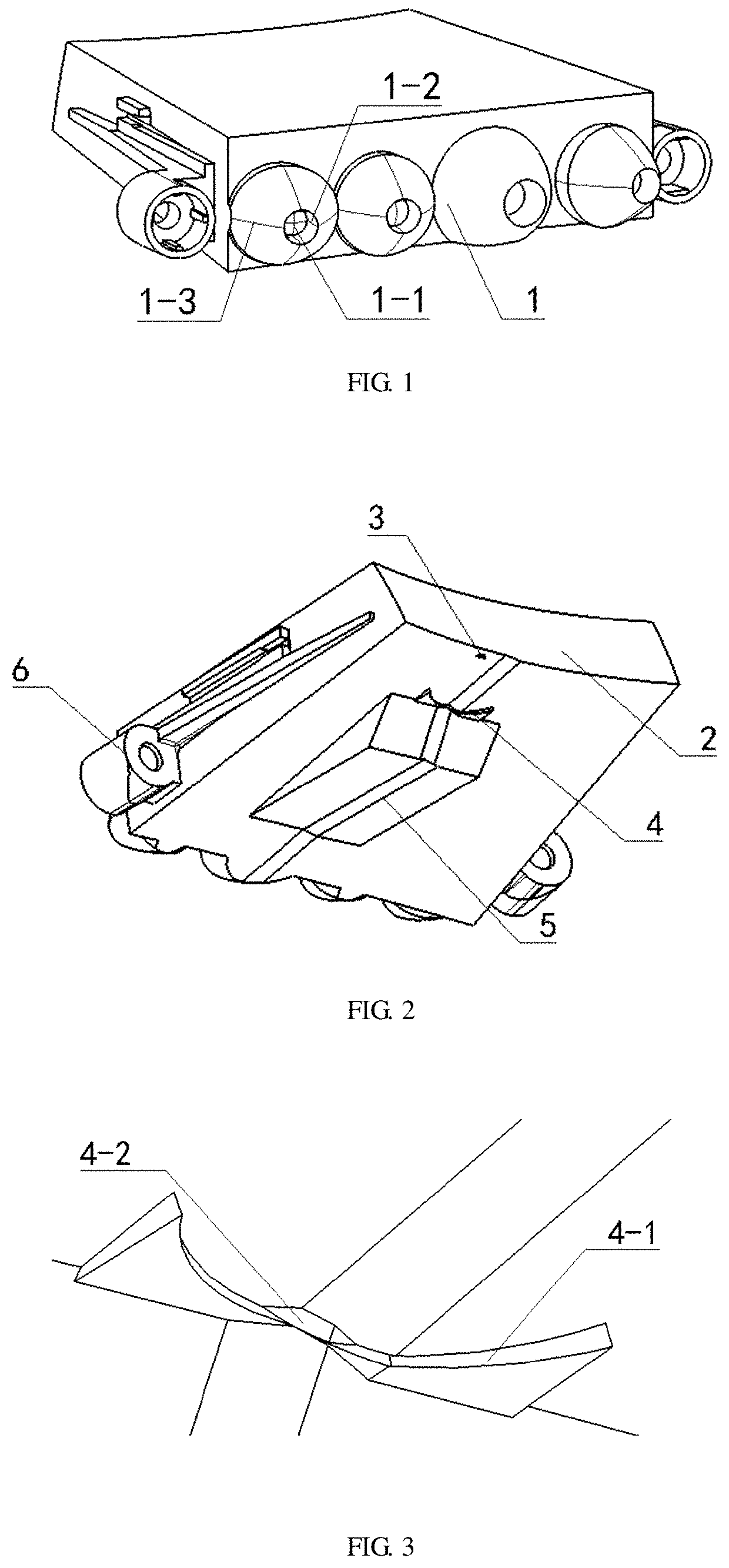
[0095]As is shown in FIG. 1 and FIG. 2, the embodiment of the invention provides a condenser for a low-beam vehicle light module, which is used for low-beam illumination of vehicles and disposed in the headlamps of the vehicles. The condenser comprises light condensing structures 1, a cut-off line forming structure 2, a 50 L dark area forming structure 3, a zone III forming structure 4, an SEG10 luminance reducing structure 5 and condenser installation structures 6. The condenser has, on the whole, a length of about 65 mm, a width of about 50 mm and a height of about 10 mm and is made from transparent plastic or resin. In the specific embodiment, the condenser is made from PC and has a refractivity of 1.586-1.587.

[0096]The light condensing structures 1 are disposed at the rear end of the condenser. The cut-off line forming structure 2 is disposed at the front end of the condenser. The SEG10 luminance reducing structure 5 is disposed at the bottom of the condenser. The zone III formi...


PUM


Abstract

A condenser for a low-beam vehicle light module comprises light condensing structures, a cut-off line forming structure, a 50L dark area forming structure, a zone III forming structure and an SEG10 luminance reducing structure. The zone III forming structure comprises a zone III breadth forming structure and an HV luminance reducing structure. The cut-off line forming structure is disposed at a front end of the condenser. The SEG10 luminance reducing structure is disposed at the bottom of the condenser. The zone III forming structure is disposed at the bottom of the condenser and is located at a front end of the SEG10 luminance reducing structure. The 50L dark area forming structure is disposed at the bottom of the condenser and is located between the zone III forming structure and the cut-off line forming structure.

Description

[0001]This application is the divisional application of U.S. Ser. No. 16 / 068,647 that is the U.S. national phase of International Application No. PCT / CN2017 / 074195 filed on 21 Feb. 2017 which designated the U.S. and claimed priority to Chinese Application Nos. CN201610866450.8 and CN201621094737.5 filed on 30 Sep. 2016, the entire contents of each of which are hereby incorporated by reference.CONDENSER FOR LOW-BEAM VEHICLE LIGHT MODULEBACKGROUND OF THE INVENTIONTechnical Field[0002]The invention relates to vehicle lights, in particular to a condenser for a low-beam vehicle light module.Description of Related Art[0003]At present, LED light sources have been maturely applied to low-beam vehicle light modules. Although various low-beam vehicle light modules provided with LED light sources have been in existence, these low-beam vehicle light modules have the development tendency of small size, simple structure, low cost and high performance and can be greatly developed on these aspects....

Claims


Application Information

Patent Timeline
IPC IPC(8): F21S41/141G02B19/00F21S41/30F21S41/20F21S41/32F21S41/27F21S41/143
CPCG02B19/0061F21S41/143G02B19/0066F21S41/285F21S41/30F21Y2115/10F21W2102/18F21S41/141F21S41/322F21S41/27F21W2102/13G02B19/0028F21S41/151F21S41/26F21W2102/135
Inventor ZHU, HEQIU, ZHIPING
Owner H A AUTOMOTIVE SYST INC
Why Eureka
Try Eureka