Hydraulic System

a hydraulic system and oil management technology, applied in the direction of machines/engines, electrochemical generators, mechanical equipment, etc., can solve the problems of preventing the safe starting of fuel cells, affecting the lubrication of aircraft, and affecting the lubrication efficiency of aircraft, etc., to achieve convenient maintenance, improve lubrication efficiency, and facilitate production

Active Publication Date: 2020-05-14
SAFRAN AERO BOOSTERS SA
View PDF0 Cites 2 Cited by
  • Summary
  • Abstract
  • Description
  • Claims
  • Application Information

AI Technical Summary

Benefits of technology

[0006]The object of the invention is to overcome at least one of the drawbacks of the prior art. More specifically, the invention aims to optimize the lubrication of an aircraft and in particular to solve the problem posed by the oil frozen at low temperature. The invention also aims to provide a compact solution, simple, lightweight, economical, reliable, easy to produce, and of convenient maintenance.

Problems solved by technology

The oil keeps the fuel cell at an optimum operating temperature, for example between 20° C. and 150° C. However, at a too low temperature the oil can freeze and clot and thus the pump cannot convey the oil, thus preventing the fuel cell from being started safely.
For that reason, some pumps are oversized to force the pumping of the oil even when frozen.
These oils include additives that make them chemically aggressive for the hydraulic system.
It is therefore difficult to balance the weight of the heating system or of the oversized pump by gaining weight on the heat exchangers.
In an aircraft equipped with a turbojet engine and a fuel cell, there are therefore two separate hydraulic circuits, each of which is particularly bulky and heavy.
This represents many parts, sometimes redundant and results in a hydraulic assembly that is bulky, expensive and heavy.

Method used


Image

  • Hydraulic System
  • Hydraulic System
  • Hydraulic System

Examples


Embodiment Construction

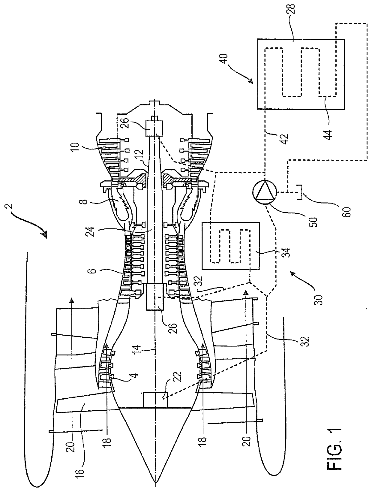
[0089]In the following description, the terms “internal” and “external” refer to a positioning relative to the axis of rotation of an axial turbomachine. The axial direction corresponds to the direction along the axis of rotation of the turbomachine. The radial direction is perpendicular to the axis of rotation. Upstream and downstream are in reference to the main flow direction of the flow in the turbomachine.

[0090]FIG. 1 is a simplified representation of an axial turbomachine 2. This is a double-flow turbojet engine. The turbojet engine 2 comprises a first compression level, called a low-pressure compressor 4, a second compression level, called a high-pressure compressor 6, a combustion chamber 8 and one or more levels of turbines 10. In operation, the mechanical power that the turbine 10 transmits to the rotor 12 sets in motion the two compressors 4 and 6. The latter comprise several rows of rotor blades associated with rows of stator blades. The rotation of the rotor about its a...


PUM


Abstract

System for an aircraft, the system comprising: a turbine engine (2) with a hydraulic lubrication circuit (30); and a fuel cell (28) with a hydraulic circuit (40) for setting and maintaining the operating temperature of the fuel cell (28); wherein the hydraulic lubrication circuit (30) and the hydraulic circuit (40) form a single and common oil circuit and the oil circuit comprises a pump (50) with a heating element integrated in the pump for heating the oil.
The pump may be an electric pump with an electric motor, wherein the electric motor comprises a coil fed with DC current forming a heating element for heating the oil.
The pump may comprise a body and the heating element may be an electric resistor embedded into the body of the pump and in direct contact with the oil.

Description

TECHNICAL FIELD[0001]The invention relates to the field of lubrication of a turbine engine. More specifically, the invention relates to the management of oil in an aircraft system.BACKGROUND ART[0002]Some aircrafts may include a fuel cell to power some equipment or contribute to fuel savings by supplementing the power needs of turbojet engines. The fuel cell, usually integrated into the fuselage, has its own oil circuit to preserve the stack of electrodes. The oil keeps the fuel cell at an optimum operating temperature, for example between 20° C. and 150° C. However, at a too low temperature the oil can freeze and clot and thus the pump cannot convey the oil, thus preventing the fuel cell from being started safely. For that reason, some pumps are oversized to force the pumping of the oil even when frozen. This means that the pump is heavier and that the mechanical stress applied to the components (pipes, valves, etc.) of the hydraulic circuit is greater. An alternative solution is t...

Claims


Application Information

Patent Timeline
Patent Type & Authority Applications(United States)
IPC IPC(8): F01D25/20F02C7/06F02C7/047F02C7/14
CPCF05D2260/213F05D2220/323F05D2240/50F02C7/14F02C7/06F02C7/047F05D2260/98F05D2230/60F01D25/20F05D2220/36F01D25/18F05D2260/205F05D2270/303F05D2220/76H01M8/00
Inventor CORNET, ALBERTRAIMARCKERS, NICOLAS
Owner SAFRAN AERO BOOSTERS SA
Why Eureka
Try Eureka