Image processing apparatus, image processing method and storage medium
a technology of image processing and image, applied in the direction of electrical apparatus, printing, pictoral communication, etc., can solve the problems of granularity worsening, the number of dots, and the dot arrangement specified by the dither matrix is not maintained, so as to reduce the density unevenness and worsen the granularity of the image
- Summary
- Abstract
- Description
- Claims
- Application Information
AI Technical Summary
Benefits of technology
Problems solved by technology
Method used
Image
Examples
first embodiment
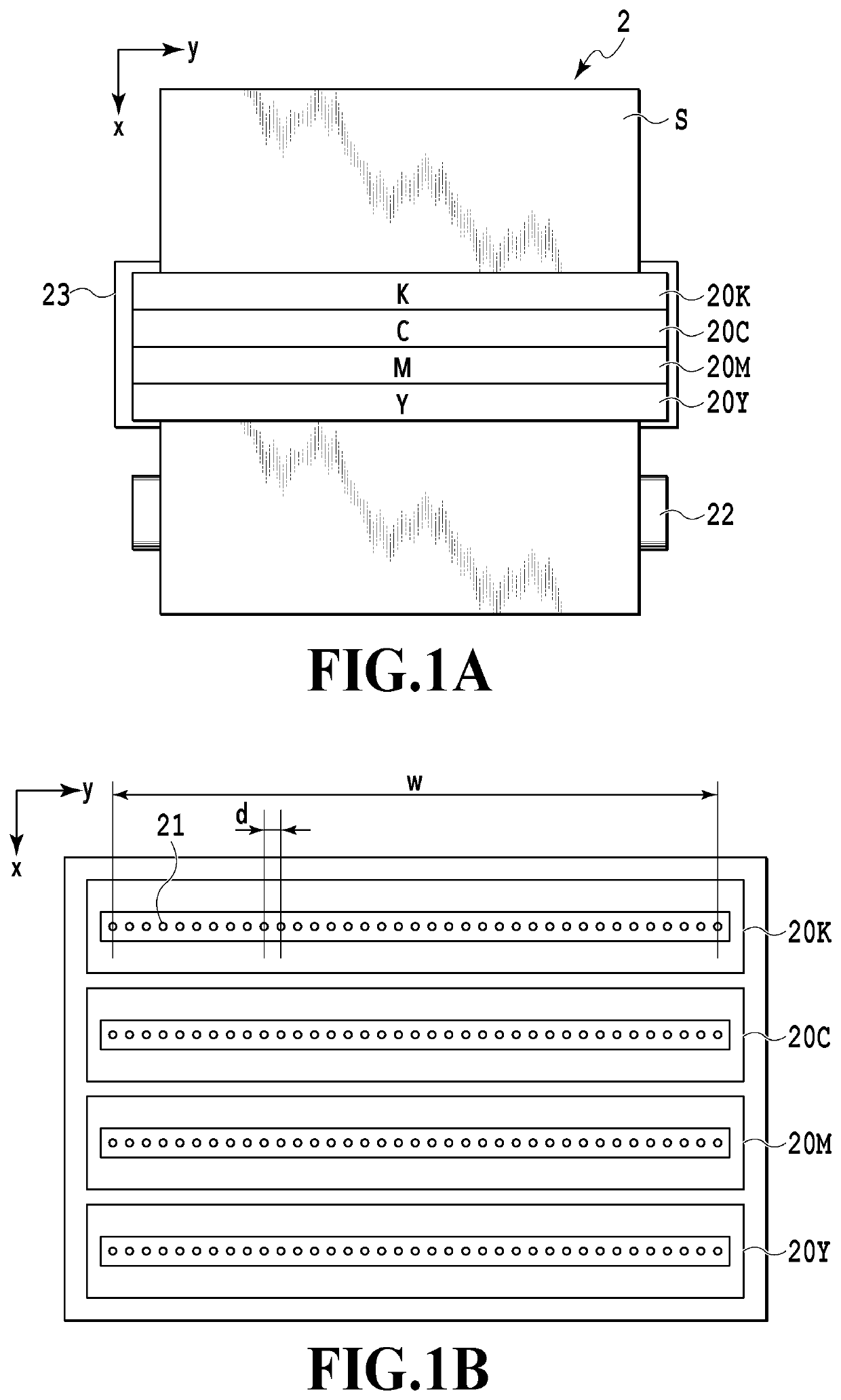
[0025]FIGS. 1A and 1B are outline configuration diagrams of an ink jet printing apparatus 2 (hereinafter, also referred to simply as printing apparatus) that is used in the present embodiment. As shown in FIG. 1A, the ink jet printing apparatus 2 mounts a print head in which nozzle rows 20K, 20C, 20M, and 20Y each ejecting black (K), cyan (C), magenta (M), and yellow (Y) inks respectively are arranged.
[0026]A conveyance roller 22 conveys a printing medium S in an x-direction at a predetermined speed. A platen 23 configured by a flat plate faces the ejection port surfaces of the nozzle rows 20K, 20C, 20M, and 20Y and supports the printing medium S that is conveyed from the rear side. The smoothness of the printing medium S in an area supported by the platen 23 is maintained and the distance from the ejection port surface is kept constant.
[0027]As shown in FIG. 1B, in each of the nozzle rows 20K, 20C, 20M, and 20Y, a plurality of nozzles 21 ejecting ink as droplets is arrayed in a y-d...
second embodiment
[0074]In the present embodiment also, like the first embodiment, it is assumed that the printing apparatus 2 explained in FIGS. 1A and 1B is used. However, in the present embodiment, it is assumed that each nozzle arrayed in the nozzle row 20 of the print head can print dots of three sizes, that is, a small dot, a medium dot, and a large dot. In the present embodiment, it is assumed that the area ratio of the small dot, the medium dot, and the large dot on a printing medium is about 1:2:3.
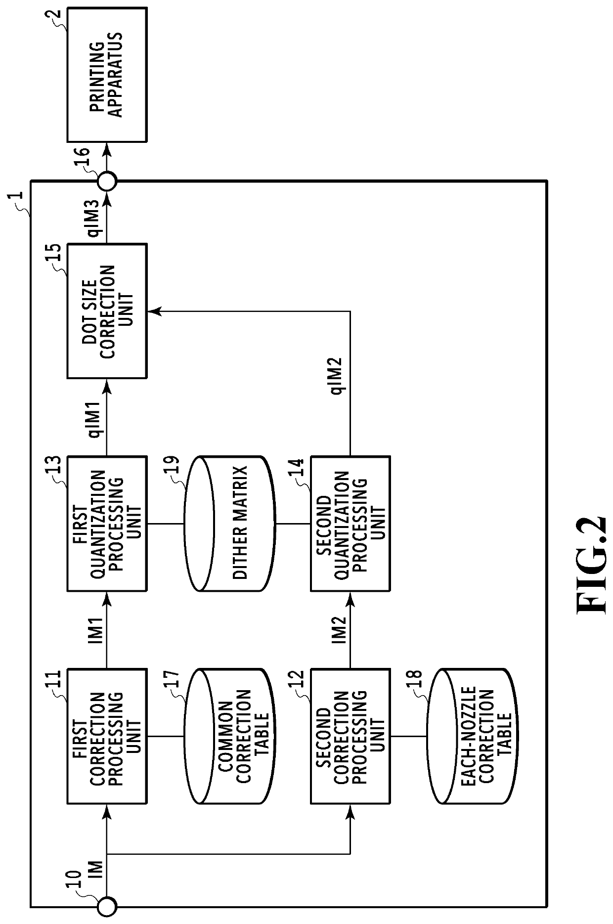
[0075]FIG. 8 is a block diagram for explaining the configuration of processing in an image processing system of the present embodiment. The processing of the first correction processing unit 11 and the second correction processing unit 12 and the contents of the correction tables 17 and 18 used by these processing units are the same as those of the first embodiment explained in FIG. 2, and therefore, explanation is omitted.
[0076]A first quantization processing unit 23 of the present embodiment sepa...
third embodiment
[0091]In the present embodiment also, like the first embodiment, the printing apparatus 2 explained in FIGS. 1A and 1B is used. Then, it is assumed that each nozzle arrayed in the nozzle row 20 of the print head can print dots of three sizes, that is, a small dot, a medium dot, and a large dot. In the present embodiment, it is assumed that the area ratio of the small dot, the medium dot, and the large dot on a printing medium is about 1:2:3.
[0092]FIG. 10 is a block diagram for explaining the configuration of processing in an image processing system of the present embodiment. The processing of the first correction processing unit 11 and the second correction processing unit 12 and the contents of the correction tables 17 and 18 used by these processing units are the same as those of the first embodiment explained in FIG. 2, and therefore, explanation is omitted.
[0093]Like the second embodiment, a first quantization processing unit 33 of the present embodiment refers to the dot size s...
PUM
 Abstract
Description
Claims
Application Information
 - R&D
- Intellectual Property
- Life Sciences
- Materials
- Tech Scout
- Unparalleled Data Quality
- Higher Quality Content
- 60% Fewer Hallucinations
Browse by: Latest US Patents, China's latest patents, Technical Efficacy Thesaurus, Application Domain, Technology Topic, Popular Technical Reports.
© 2025 PatSnap. All rights reserved.Legal|Privacy policy|Modern Slavery Act Transparency Statement|Sitemap|About US| Contact US: help@patsnap.com


