Acoustic Absorption Structure Comprising At Least One Rotationally-Indexed Acoustic Element And Aircraft Propulsion Assembly Comprising Said Acoustic Absorption Structure

Active Publication Date: 2020-05-28
AIRBUS OPERATIONS (SAS)
View PDF0 Cites 1 Cited by
  • Summary
  • Abstract
  • Description
  • Claims
  • Application Information

AI Technical Summary

Benefits of technology

[0012]According to an embodiment of the invention, the acoustic absorption structure comprises a drainage system which comprises at least one first drainage orifice passing through the enclosure and a rotational indexing system making it possible to position the acoustic element in the support layer so that at

Problems solved by technology

To attenuate such soundwaves, the honeycomb cellular layer needs to have a significant height which is detrimental in

Method used


Image

  • Acoustic Absorption Structure Comprising At Least One Rotationally-Indexed Acoustic Element And Aircraft Propulsion Assembly Comprising Said Acoustic Absorption Structure
  • Acoustic Absorption Structure Comprising At Least One Rotationally-Indexed Acoustic Element And Aircraft Propulsion Assembly Comprising Said Acoustic Absorption Structure
  • Acoustic Absorption Structure Comprising At Least One Rotationally-Indexed Acoustic Element And Aircraft Propulsion Assembly Comprising Said Acoustic Absorption Structure

Examples


first embodiment

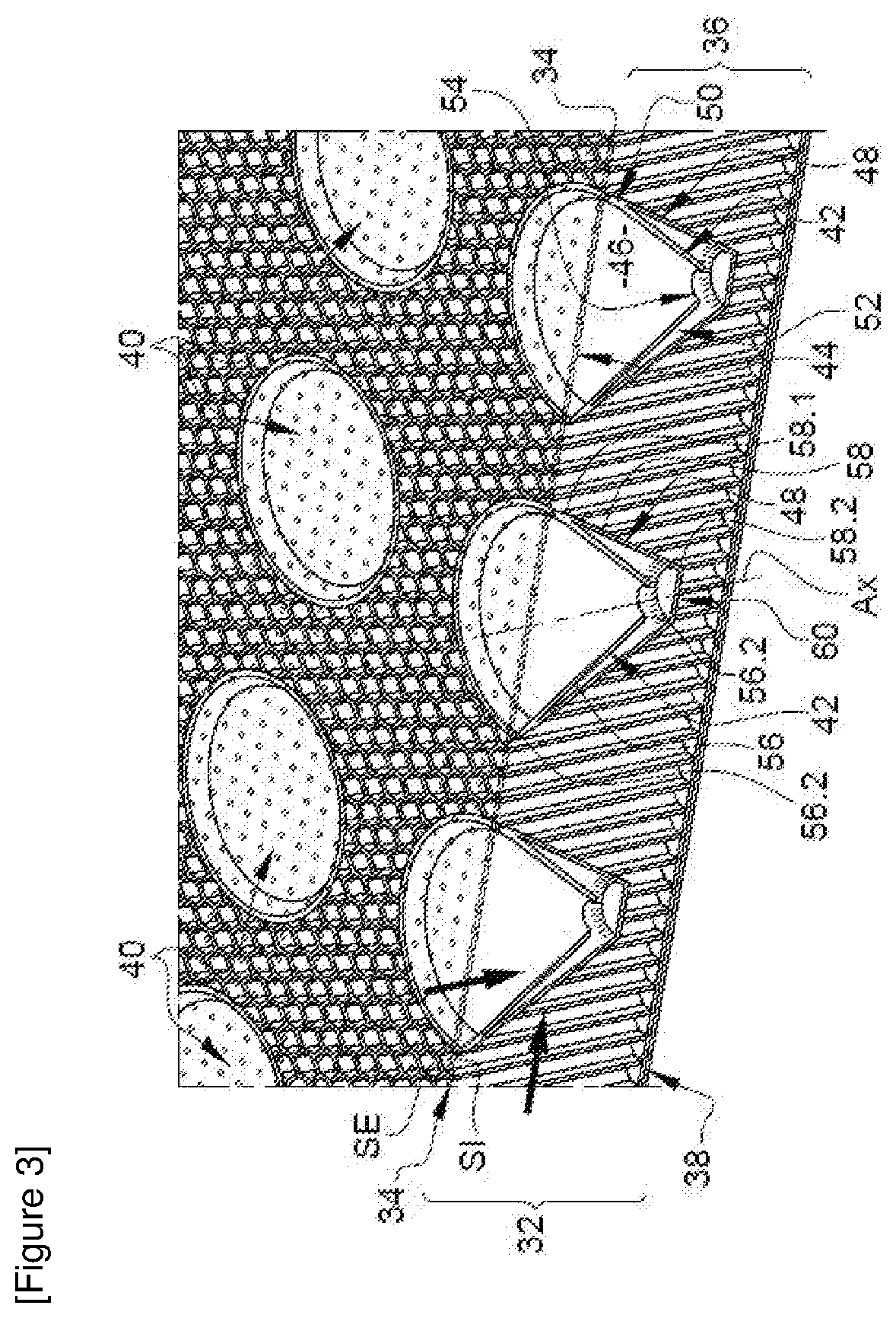
[0069] visible in FIGS. 6, 8 to 11, the second enclosure 48 comprises two diametrically opposite drainage orifices 64, 64′. In this case, the acoustic element 40 must be correctly oriented for one of the two drainage orifices 64, 64′ to be positioned at or in proximity to a low point of the second cavity 52 in order for the volume of liquid stagnating inside the second cavity 52 to be as small as possible. To this end, the acoustic absorption structure 30 comprises a rotational indexing system 66 configured to position the acoustic element 40 according to two given positions with respect to the support layer 36.

[0070]According to the first embodiment, the rotational indexing system 66 comprises, at the acoustic element 40, the outer lateral wall 58 of the second enclosure 48 which has two planes of symmetry P1 and P2 and, at the support layer 36, an indentation 62 which has forms complementary or identical to those of the outer lateral wall 58 of the second enclosure 48.

[0071]Accord...

second embodiment

[0072] visible in FIG. 9, the second edge 58.2 of the outer lateral wall 58 describes an oblong form which has two planes of symmetry P1 and P2 and comprises two rectilinear and parallel sections 68.1, 68.2 linked by two semi-circular sections 68.3, 68.4.

[0073]According to these two embodiments, the outer lateral wall 58 has a set tubular surface which bears at a first end on the first circular edge 58.1 and at a second end on the second edge 58.2. The outer lateral wall 58 is not of revolution.

[0074]According to these two embodiments, the two drainage orifices, 64, 64′ are positioned with respect to the planes of symmetry of the outer lateral wall 58 of the second enclosure 48 so that one of the two drainage orifices 64, 64′ is positioned at or in proximity to the low point of the second cavity 52 when the acoustic element is in its indentation 62.

[0075]According to one configuration, the straight line passing through the two drainage orifices 64, 64′ is contained in one of the pla...

third embodiment

[0077] visible in FIG. 13, the second enclosure 48 comprises a single drainage orifice 64. In this case, the acoustic element 40 must be correctly oriented for the single drainage orifice 64 to be positioned at or in proximity to a low point of the second cavity 52 in order for the volume of liquid stagnating inside the second cavity 52 to be as small as possible. To this end, the acoustic absorption structure 30 comprises a rotational indexing system 66 configured to position the acoustic element 40 according to a single givenposition with respect to the support layer 36.

[0078]According to the third embodiment visible in FIG. 13, the rotational indexing system 66 comprises a first form, called polarizing means 70, integral to the acoustic element 40, protruding with respect to the outer lateral wall 58, and a second form, called recess 72, hollowed out in the support layer 36, the polarizing means 70 and the recess 72 having complementary or identical forms so that the acoustic ele...


PUM


Abstract

An acoustic absorption structure includes: at least one acoustic element which has at least one cavity delimited by at least one enclosure comprising at least one first drainage orifice passing through the enclosure, and a rotational indexing system making it possible to position the acoustic element so that at least one first drainage orifice is positioned in proximity to or at a lowest point of the cavity. An aircraft propulsion assembly including such an acoustic absorption structure is also described.

Description

FIELD OF THE INVENTION[0001]The present application relates to an acoustic absorption structure comprising at least one rotationally-indexed acoustic element and a propulsion assembly comprising such an acoustic absorption structure.BACKGROUND OF THE INVENTION[0002]According to an embodiment of the prior art, a propulsion assembly comprises a nacelle and a turbofan engine, positioned inside the nacelle. Some surfaces of the nacelle and of the turbofan engine comprise acoustic absorption structures for attenuating the sound nuisances. According to one embodiment, an acoustic absorption structure comprises a porous layer, a honeycomb cellular layer and a reflective layer.[0003]An ultrahigh bypass ratio (UHBR) turbofan engine has a fan revolving at lower frequencies than some turbofan engines currently on the market so that the acoustic absorption structures have to be configured to attenuate low frequency soundwaves. To attenuate such soundwaves, the honeycomb cellular layer needs to ...

Claims


Application Information

Patent Timeline
IPC IPC(8): B64D33/02G10K11/172G10K11/168
CPCB32B2605/18B32B3/30G10K11/172B32B2307/102B64D2033/0206G10K11/168B64D33/02B64D2033/0286B64D33/06F02C7/24F02K1/827F05D2260/602Y02T50/60
Inventor BROCHARD, WOLFGANGCAZEAUX, LAURENTMAFFRE, CLAIRE
Owner AIRBUS OPERATIONS (SAS)
Why Eureka
Try Eureka