USB control circuit

Active Publication Date: 2020-06-04
REALTEK SEMICON CORP
View PDF6 Cites 1 Cited by
  • Summary
  • Abstract
  • Description
  • Claims
  • Application Information

AI Technical Summary

Benefits of technology

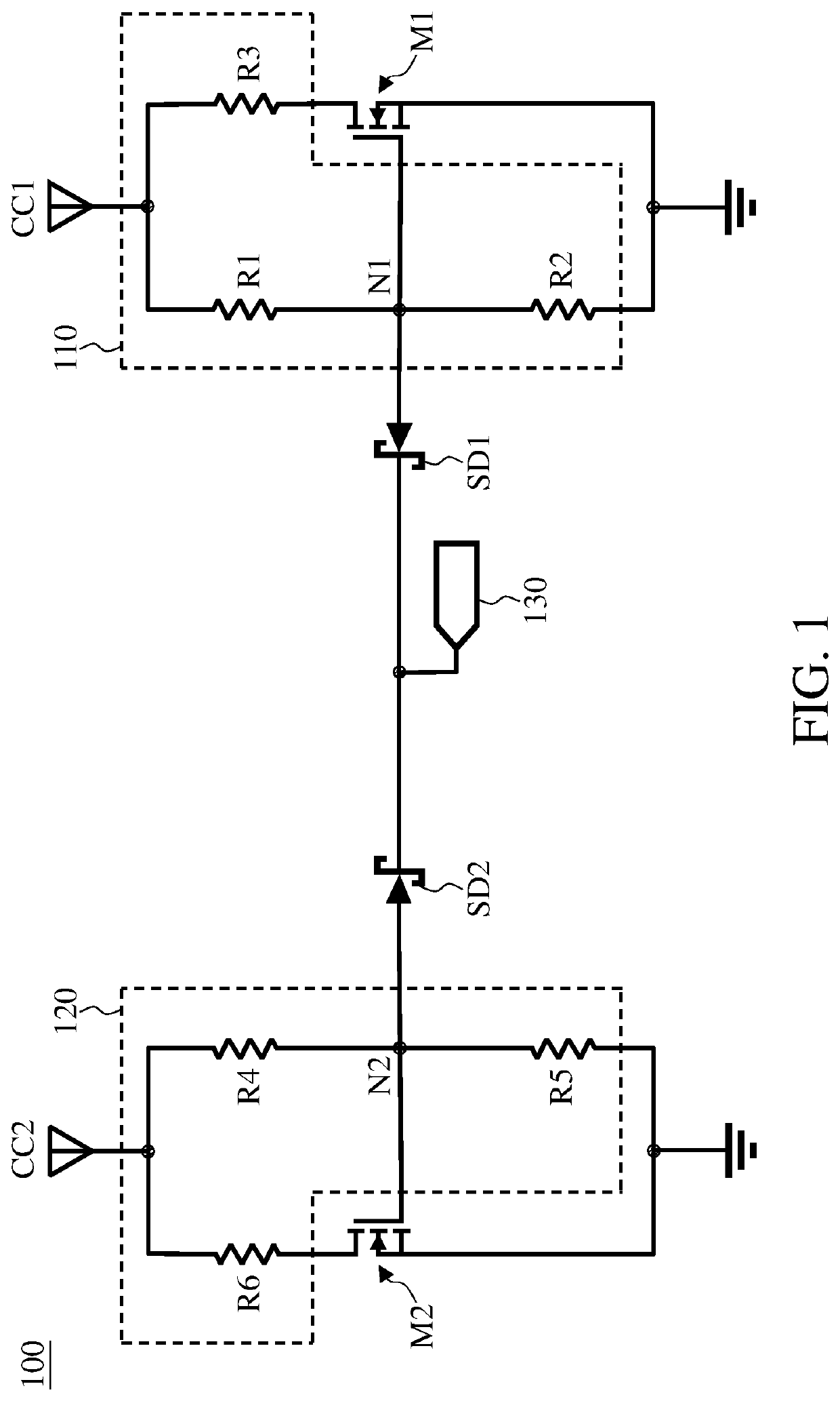
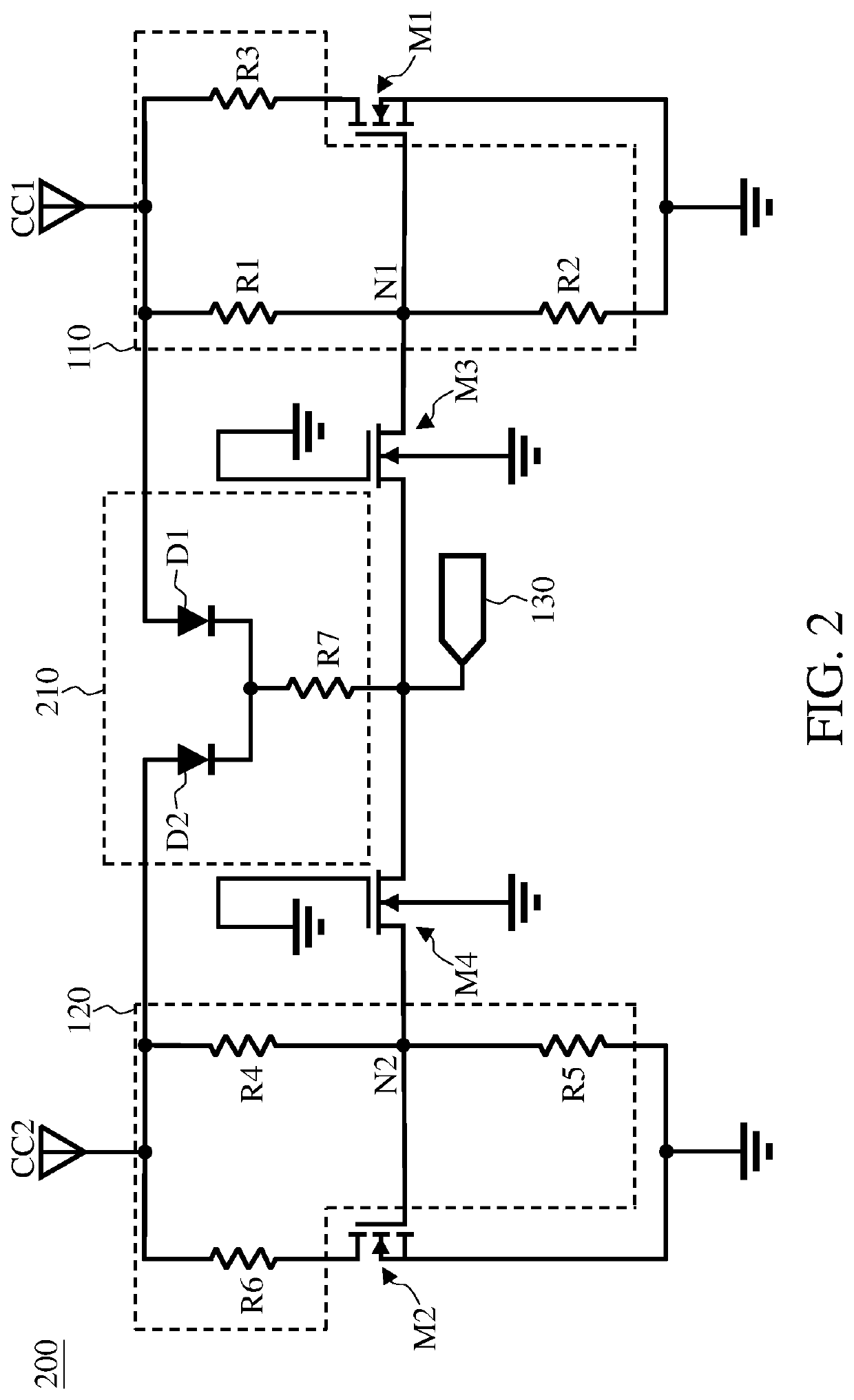
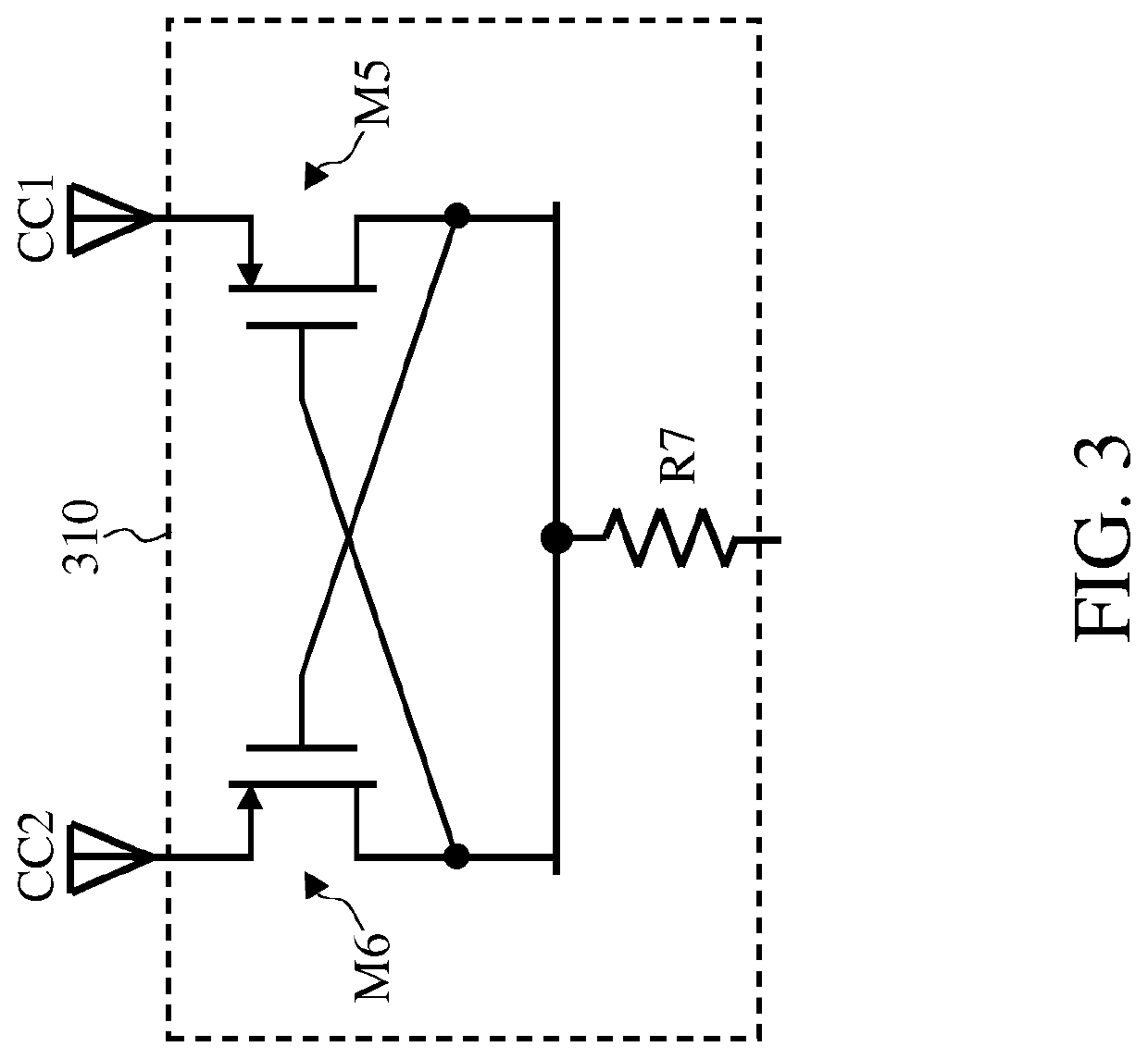
The present invention is a USB control circuit that uses one pin to control the two pins (CC1 and CC2) of USB type-C. Compared to previous technology, this circuit is cheaper, smaller, and allows for separate adjustment of the input impedance of the two pins. As a result, it provides a more flexible and efficient solution for controlling USB data transfer.

Problems solved by technology

The conventional USB type-C control chip uses two pins to respectively control the CC1 pin and the CC2 pin, that is, the conventional USB type-C control circuit controls the CC1 pin and the CC2 pin individually, which increases the circuit area and cost of the control chip.
However, if the USB control chip uses a single pin to control both the CC1 pin and the CC2 pin, the input resistance of the CC1 pin or the CC2 pin may probably fail to conform to the USB type-C specifications.

Method used


Image

  • USB control circuit
  • USB control circuit
  • USB control circuit

Examples


Embodiment Construction

[0012]The following description is written by referring to terms of this technical field. If any term is defined in this specification, such term should be explained accordingly. In addition, the connection between objects or events in the below-described embodiments can be direct or indirect provided that these embodiments are practicable under such connection. Said “indirect” means that an intermediate object or a physical space exists between the objects, or an intermediate event or a time interval exists between the events.

[0013]The disclosure herein includes USB control circuits. On account of that some or all elements of the USB control circuits could be known, the detail of such elements is omitted provided that such detail has little to do with the features of this disclosure and this omission nowhere dissatisfies the specification and enablement requirements. A person having ordinary skill in the art can choose components or steps equivalent to those described in this speci...


PUM


Abstract

The invention discloses a control circuit applied to a Universal Serial Bus (USB) which includes a first channel configuration pin and a second channel configuration pin. The control circuit includes: a first transistor having a first control terminal; a first resistor group coupled to the first channel configuration pin and the first transistor; a first Schottky diode having a first end and a second end, the first end being coupled to the first control terminal; a second transistor having a second control terminal; a second resistor group coupled to the second channel configuration pin and the second transistor; and a second Schottky diode having a third end and a fourth end, the third end being coupled to the second control terminal, and the fourth end being coupled to the second end of the first Schottky diode.

Description

BACKGROUND OF THE INVENTION1. Field of the Invention[0001]The present invention generally relates to Universal Serial Bus (USB) and, more particularly, to USB control circuits.2. Description of Related Art[0002]Universal Serial Bus (USB) Type-C has two channel configuration pins: the first channel configuration pin (hereinafter referred to as CC1 pin) and the second channel configuration pin (hereinafter referred to as CC2 pin). When first USB equipment (e.g., a host or a device) is connected to second USB equipment (e.g., a device or a host), the first USB equipment may need to receive power from the second USB equipment (e.g., the first USB equipment is a mobile phone, and the second USB equipment is a computer), or the first USB device does not need to receive power from the second USB equipment (e.g., the first USB equipment is a monitor and the second USB equipment is a mobile phone). According to the USB type-C specifications, in cases where the first USB equipment needs to re...

Claims


Application Information

Patent Timeline
IPC IPC(8): G06F13/42H03K17/687
CPCG06F13/4282H03K17/6871G06F2213/0042
Inventor CHEN, LEAF
Owner REALTEK SEMICON CORP
Why Eureka
Try Eureka