
Improved Duster Flat Support

a technology of flat support and duster, which is applied in the direction of floor cleaners, carpet cleaners, brushes, etc., can solve the problems of affecting the use of the device, and extending beyond the position of the dusting surface,

Inactive Publication Date: 2020-06-11
ZORZO MARCO
View PDF0 Cites 0 Cited by
  • Summary
  • Abstract
  • Description
  • Claims
  • Application Information

AI Technical Summary

Benefits of technology

The invention is a duster that can clean large surfaces without scratching them. It can also ensure the use of the cloth on both main and opposite surfaces of the plate. The duster is easy to adjust the inclination and works without interfering beyond the position of the active surface of the plate. The interconnecting devices allow the cleaning surface to be continuous and without discontinuity for the support of the cloth. The retention device facilitates the correct extraction sideshift movement, the relative rotation, and the subsequent insertion and repositioning movement of the insert into its seat.

Problems solved by technology

With respect to what is stated in the aforesaid patent, the duster has the drawback that the thickness of the adjustable hinge of the inclination between the handle and the laminar plate is greater than the thickness of the plate and protrudes beyond the position of the dusting surface.
This aforesaid positioning of the adjustable hinge with an axis corresponding to that of the plate entails, in fact, a considerable limitation to the use of said device, which cannot work freely on surfaces extending beyond the extension of the plate without the peripheral part of the adjustable hinge scraping along the floor.
There would be a possible solution in decreasing the diametric extension of the hinge, bringing its thickness within the overall dimensions of the plate, in this way compromising the reliability of the device for a unit load on the materials beyond their breaking strength.
Or, alternatively, another possible solution would be to increase the thickness of the plate beyond the maximum overall size of the hinge, in this way losing portability and the ease of movement of the manual cleaning tool.
Alternatively, it is possible to redesign the cleaning tool to overcome this problem by moving the adjustable hinge to one side so that it does not protrude beyond the dusting surface, however this introduces a further limitation of this cleaning tool, limiting the free dusting to just one side and using only half of the surface of the cloth that covers the duster.
For all the aforementioned reasons, this cleaning tool has met with little success to date, even if there is great demand for a tool that can remove dust on large surfaces without the risk of scratching.

Method used


Image

  • Improved Duster Flat Support
  • Improved Duster Flat Support
  • Improved Duster Flat Support

Examples


Embodiment Construction

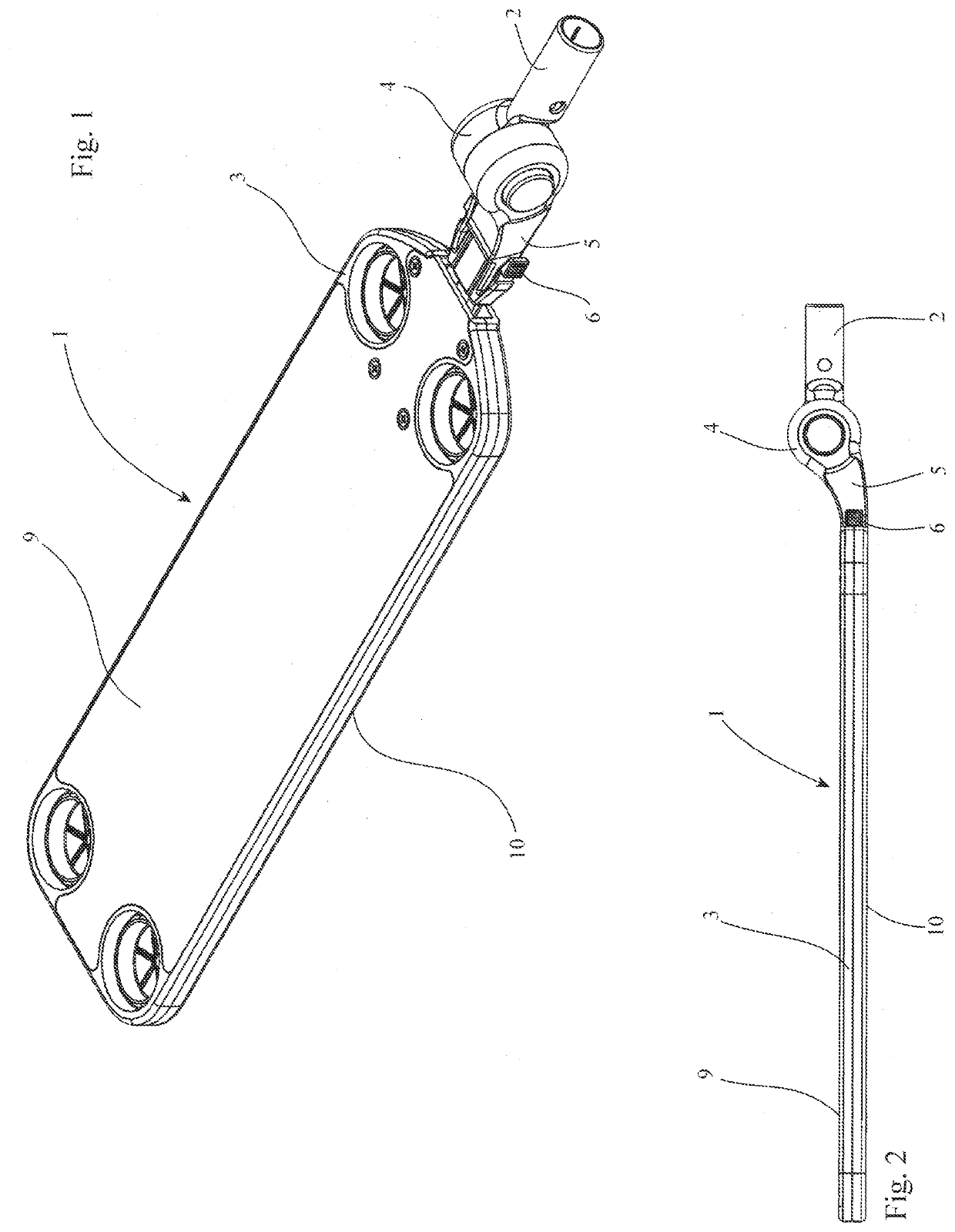
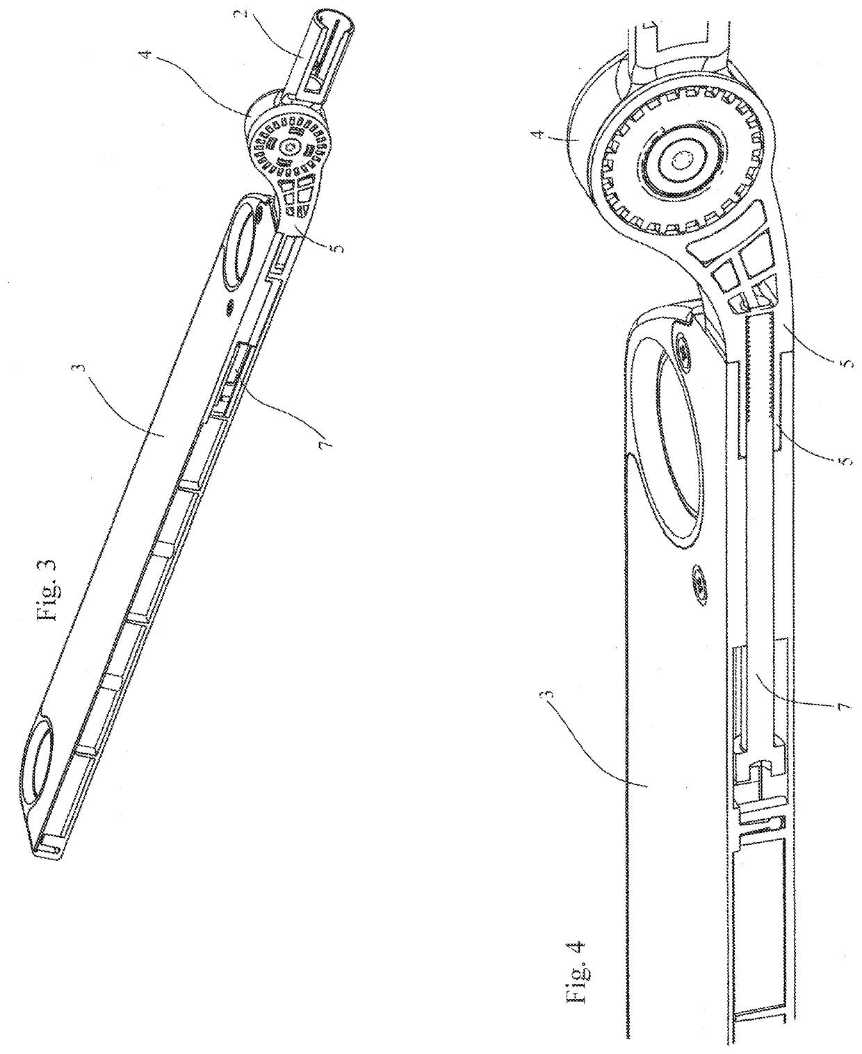
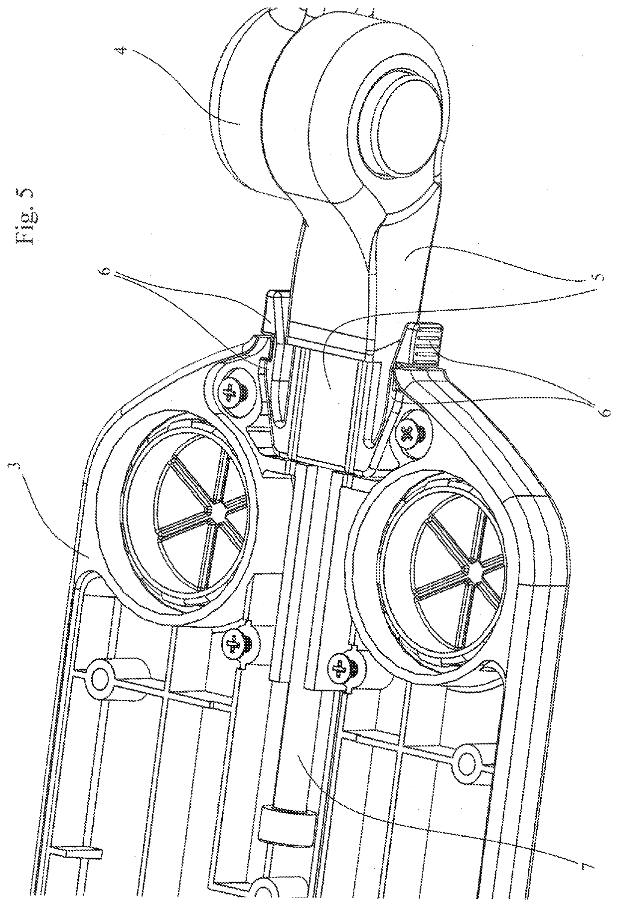
[0038]With reference to the figures, a duster 1 is shown comprising a flat laminar element extended in length, called a plate 3, which is connected to and operated by a handle 2 by means of an adjustable hinge 4.

[0039]Said hinge 4 allows the angle of the handle 2 to be changed with respect to the plate 3.

[0040]Said hinge 4 is not on the main axis of the plate 3, but is offset to the side, so that the duster can slide freely on a surface to be cleaned without the risk that a protruding part of the hinge comes into contact with the surface, with possible scratching.

[0041]To address the fact that both the larger surfaces 9, 10 of the duster can be active cleaning surfaces, using both sides of the cloth positioned on them, the part of the hinge 4 that connects to the plate 3 is not fixed but can be detached and rotated, turning upside down the hinge 4 and bringing the space it occupies from a first side to a second side, opposite the first side with respect to the main axis of the plate...


PUM


Abstract

This is an improved cleaning tool, called a duster, whose offset hinging can rotate around an axis to shift its footprint outside the position of the cleaning surfaces.

Description

CROSS-REFERENCE TO RELATED APPLICATIONS[0001]This application claims the benefit of Italian Patent Application 102017000054257, filed on May 18, 2017, and PCT Application PCT / IB2018 / 053305, filed on May 11, 2018, both incorporated herein by reference.STATEMENT REGARDING FEDERALLY SPONSORED RESEARCH AND DEVELOPMENT[0002]Not Applicable.FIELD OF THE INVENTION[0003]This invention relates to an improved cleaning tool, more specifically to an improved duster.BACKGROUND[0004]With respect to what is stated in the aforesaid patent, the duster has the drawback that the thickness of the adjustable hinge of the inclination between the handle and the laminar plate is greater than the thickness of the plate and protrudes beyond the position of the dusting surface. This aforesaid positioning of the adjustable hinge with an axis corresponding to that of the plate entails, in fact, a considerable limitation to the use of said device, which cannot work freely on surfaces extending beyond the extensio...

Claims


Application Information

Patent Timeline
IPC IPC(8): A47L13/38A47L13/42A47L13/16A46B5/00
CPCA47L13/38A46B5/0058A47L13/42A47L13/16
Inventor ZORZO, MARCO
Owner ZORZO MARCO
Learn More