Electrical machine stator assembly

a technology for stators and electric machines, applied in the direction of dynamo-electric machines, electrical apparatus, magnetic circuits, etc., can solve the problems of reducing efficiency, noise, and difficulty in placing windings on the ferromagnetic cor

Inactive Publication Date: 2012-05-10
WELLINGTON DRIVE TECHNOLOGIES
View PDF0 Cites 3 Cited by
  • Summary
  • Abstract
  • Description
  • Claims
  • Application Information

AI Technical Summary

Benefits of technology

[0028]In a further embodiment the invention consists of an electrical machine having a rotor having multiple poles adjacent a stator consisting of multiple core portions assembled in the form of a toroidal core, each core portion having configurations which limit engagement of the core portions with each other and limit excursions of one core portion relative to the other in a radial direction with respect to the axis of the core, each core portion having one or more windings, the core portion lengths being such that the configurations for the core portions fall equally within each phase of the stator, the configurations of the abutting region of each core portion overlapping with the next core portion such that the sum of the overlaps approximates a multiple of 180 electrical degrees.

Problems solved by technology

Such machines use less iron than a typical radial pole machine but provide difficulties in either placing the windings on the ferromagnetic core or in placing the core within the windings.
Leaving a gap in a core provides a discontinuity in the magnetic flux at this point, which reduces efficiency and tends to aggravate cogging of the motor, making it move with regular jerk overlays on the smooth torque and creating noise.
Bending the core requires the core to be flexible in the radial direction, which requires a core material having a less favourable cost performance ratio than conventional stacked laminations.
However joints between segments inevitably cause discontinuities in the magnetic flux due to imperfections in fit.
This results in the discontinuities being unevenly magnetically distributed, causing variations in magnetic circuit reluctance as the rotor rotates.
This again causes cogging and vibration.
However for numbers of poles less than 16, the angle subtended by a complete pole is large enough to make a joint of this length impractical to manufacture and assemble without flexing the core.

Method used


Image

  • Electrical machine stator assembly
  • Electrical machine stator assembly
  • Electrical machine stator assembly

Examples


Embodiment Construction

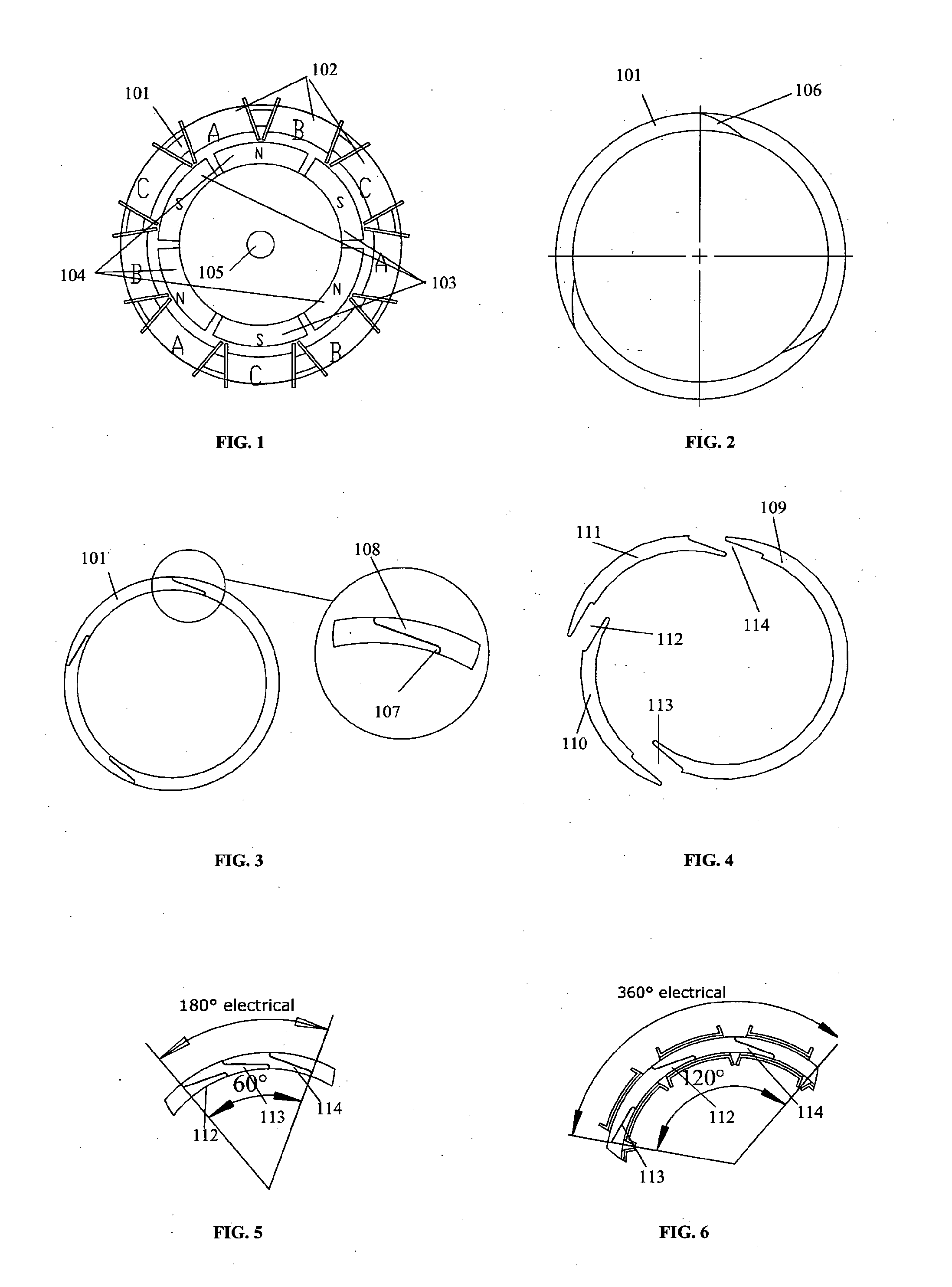
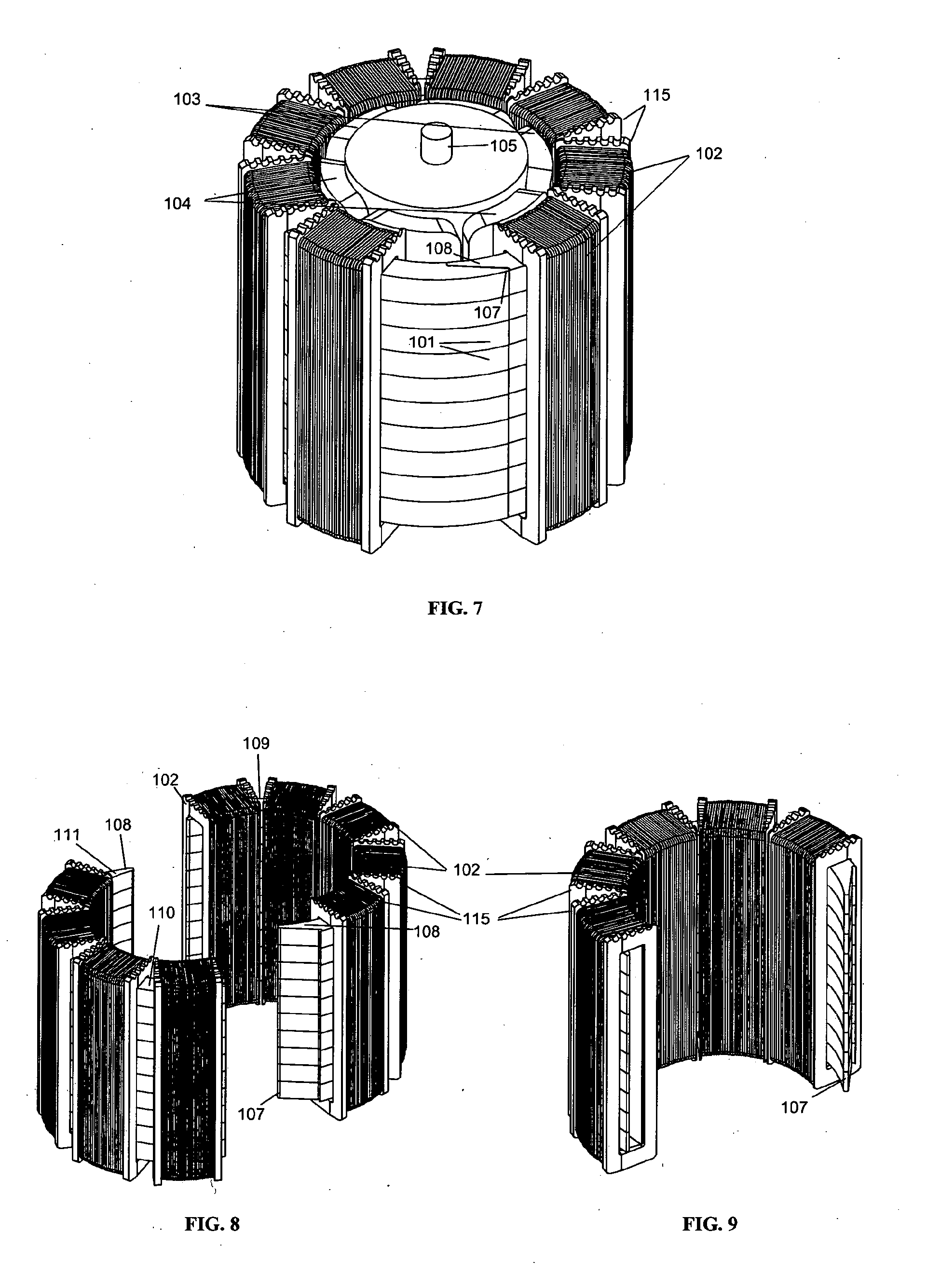
[0045]Referring now to FIG. 1 this shows a plan view of a six pole motor with three phases. The poles are formed by pairs of south outwards magnets 103 and north outwards magnets 104. The phases are provided by three sets of the three phases 102 on toroidal bobbins A, B and C on a ferromagnetic or ferrimagnetic stator core 101, so that there is a set of three phases for each consecutive set of two magnets. Each bobbin of a phase will subtend two-thirds of the width of a pole magnet and 360 electrical degrees will subtend the three bobbins of a phase set, or 120 mechanical degrees. The magnets may be ferritic ceramic, rare earth or iron based.

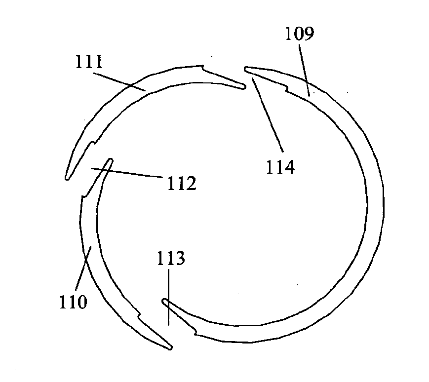
[0046]To allow assembly of the core with the bobbins already in place the core 101 may be assembled in segments as described in the known prior art. Such segments typically are joined by simply abutting the radial faces of the segments, or using axially assembled dovetail joints. In either case this leaves at least two radial air gaps in the cor...


PUM

PropertyMeasurementUnit
circumferential lengthsaaaaaaaaaa
electrical degreesaaaaaaaaaa
lengthaaaaaaaaaa

Abstract

An electrical machine such as a motor has a stator on which toroidal coils are mounted on a segmented backiron. The segments overlap to produce a graded magnetic flux at the joint between two segments, and the number of segments and the position of the joints with respect to the phases of the machine coils and the poles of the rotor are such that the flux joints are distributed evenly across the phases and the poles while allowing assembly of the machine backiron with the coils mounted on the segments. This results in a motor with no sudden flux changes in the stator and therefore reduced cogging and incipient noise.

Description

TECHNICAL FIELD[0001]The invention generally relates to stators for electrical or electrodynamic machines. More particularly the invention relates to stators for electrical motors and generators where the stator carries windings supported on a toroidal back iron.BACKGROUND ART[0002]Motors or generators where the windings are supported on a ferromagnetic substantially toroidal back iron are known. Such machines use less iron than a typical radial pole machine but provide difficulties in either placing the windings on the ferromagnetic core or in placing the core within the windings.[0003]It is known to wind windings on a toroidal core, whether with or without bobbins, by using a special winding machine which, effectively, rotates through and around the toroidal core. Similarly it is known to place the core within a series of wound bobbins by threading wound bobbins on through a gap in the core, this gap being left open, or closed by bending the core.[0004]Motor designs of this type a...

Claims


Application Information

Patent Timeline
Patent Type & Authority Applications(United States)
IPC IPC(8): H02K1/06H02K15/04
CPCH02K1/12Y10T29/49009H02K15/02H02K3/46
Inventor GERMANN, TIMOTHY SCOTT
Owner WELLINGTON DRIVE TECHNOLOGIES
Why Eureka
Try Eureka