Bit-synchronous feedback control of receiver sensitivity

a bit-synchronous feedback and receiver technology, applied in the field of receivers, can solve problems such as misinterpretation of apparent signals, and achieve the effects of improving the noise performance of the receiver, reducing bandwidth, and increasing sensitivity

Active Publication Date: 2013-09-17
RECEIVERS UNLIMITED
View PDF6 Cites 2 Cited by
  • Summary
  • Abstract
  • Description
  • Claims
  • Application Information

AI Technical Summary

Benefits of technology

[0010]The needs remaining in the prior art are addressed by the present invention, which relates to a receiver arrangement and, more particularly, to a receiver with increased sensitivity realized by improving the noise performance of the receiver without excessive spreading of the received bits into the neighboring bits (as might be caused, for example, by just reducing the bandwidth).

Problems solved by technology

If the receiver is presented with a signal below its sensitivity limits, it will have a much higher BER, since random fluctuations (generally attributed to “noise sources” in the receiver) will cause the apparent signal to be mis-interpreted upon occasion.

Method used


Image

  • Bit-synchronous feedback control of receiver sensitivity
  • Bit-synchronous feedback control of receiver sensitivity
  • Bit-synchronous feedback control of receiver sensitivity

Examples


Embodiment Construction

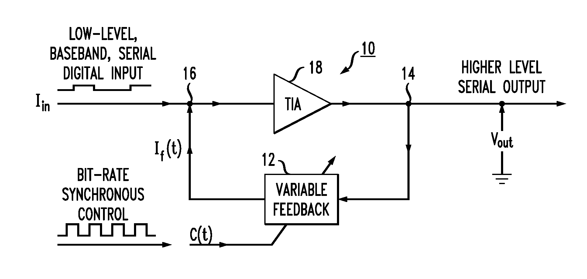
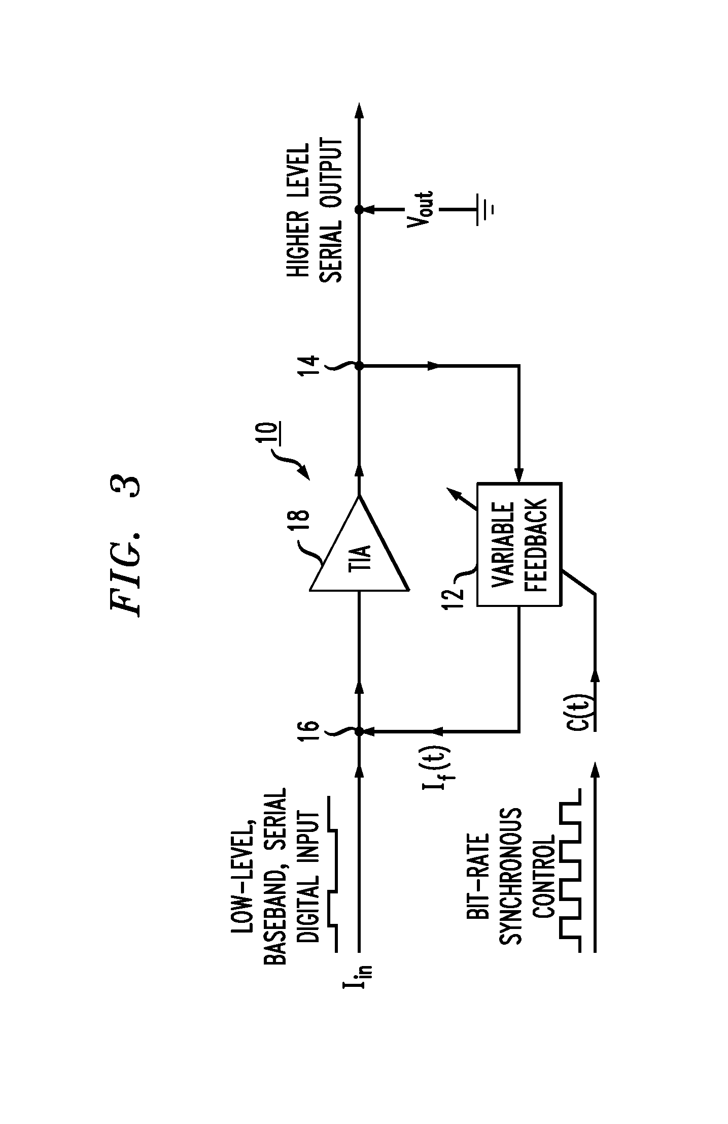
[0026]As is known in the art, improving receiver sensitivity is related to maximizing the signal-to-noise ratio (SNR) for the weak signals presented to the receiver. An important aspect to maximizing the SNR is to minimize noise sources at locations where the data signal is weakest, for example, at the input to the receiver gain stage.

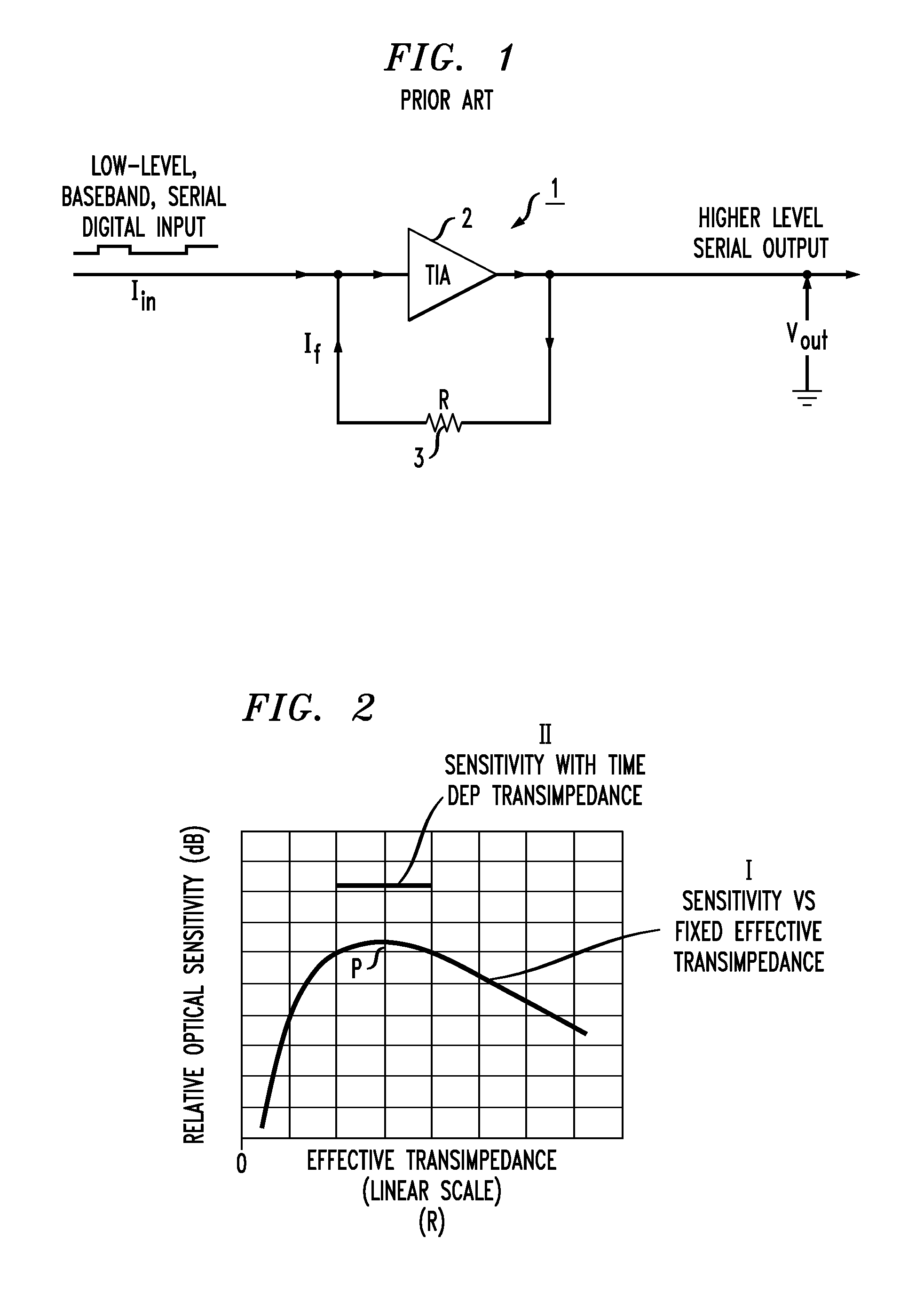
[0027]FIG. 1 illustrates an exemplary prior art receiver gain stage 1 in the form of a transimpedance amplifier (TIA) 2 and a resistive feedback element 3. Feedback element 3 provides a feedback current If in response to the output voltage Vout from TIA 2. Assuming that the gain of TIA 2 is very large, the effect of this feedback is that output voltage Vout is defined as follows:

Vout=Iin*R,

where R is the resistance value associated with element 3 and Iin is defined as the input current applied to TIA 2.

[0028]It is to be understood that the signs of Iin and Vout are selected to be of opposite polarity; that is, if Iin is flowing away from TIA 2, voltag...


PUM


Abstract

A receiver including an amplifying section for converting a relatively low power digital input signal into a relatively high power digital output signal is configured to utilize an adjustable feedback signal that is synchronous with the bit rate of the incoming digital signal so as to modify the level of the feedback signal as a function of time along the width of each bit of the digital input signal, increasing the bandwidth of the receiver at the leading edge of each incoming bit and decreasing the bandwidth otherwise.

Description

CROSS-REFERENCE TO RELATED APPLICATIONS[0001]This application claims the benefit of U.S. Provisional Application No. 61 / 361,692, filed Jul. 6, 2010 and herein incorporated by reference.TECHNICAL FIELD[0002]The present invention relates to receivers used in digital systems and, more particularly, to an arrangement for providing bit-synchronous modulation of feedback within the receiver in order to improve the sensitivity of the receiver.BACKGROUND OF THE INVENTION[0003]Digital data is stored and transferred for many applications. Communications is becoming more and more digital. For example, telephony, which was originally analog throughout the world is now almost totally digital. Also, musical performances are now digitally recorded and distributed on CDs. Visual material that had previously been distributed via film and / or VHS tape is now contained on DVDs and Blue Ray disks; television broadcasting has now also entered the digital domain.[0004]Analog “front ends” for digital recei...

Claims


Application Information

Patent Timeline
Patent Type & Authority Patents(United States)
IPC IPC(8): H04L27/08
CPCH03G3/3084H04B10/6932
Inventor FRENCH, JOHN SARGENTBERGMANN, ERNEST EISENHARDT
Owner RECEIVERS UNLIMITED
Why Eureka
Try Eureka