Power assist suit

a technology of assist suit and assist belt, which is applied in the field of power assist suit, can solve the problems of not being able to follow the variation in distance either. , to achieve the effect of reducing the transmission efficiency of assist torque and breaking of cables

Active Publication Date: 2020-06-11
JTEKT CORP
View PDF0 Cites 14 Cited by
  • Summary
  • Abstract
  • Description
  • Claims
  • Application Information

AI Technical Summary

Benefits of technology

[0008]The present disclosure can appropriately maintain a worn state of the thigh-worn parts worn on the thighs of a wearer in response to various motions of the thighs so as to efficiently transmit assisting torque.
[0020]In this configuration, the cable drawn out of the drive pulley is guided by the cable guide to the cable hole in a straight line. Thus, the cable is not subjected to a force in a straining direction, so that a decrease in the assisting torque transmission efficiency, breakage of the cable, etc can be prevented.

Problems solved by technology

With the (right) leg belt worn around and fixed to the (right) thigh of the wearer and the (left) leg belt worn around and fixed to the (left) thigh of the wearer, the structure of the motion assisting device described in JP 2018-149624 A does not allow the (right) leg belt and the (left) leg belt to slide in the longitudinal direction of the thighs.
It is disadvantageous that the (right) leg belt and the (left) leg belt cannot slide in the longitudinal direction of the thighs and therefore cannot follow this variation in distance.
It is disadvantageous that the (right) leg belt and the (left) leg belt cannot slide in the longitudinal direction of the thighs and therefore cannot follow this variation in distance either.
When these leg belts cannot follow the variation in distance, assisting torque may not be efficiently transmitted.
Moreover, these leg belts may be forcibly moved along the thighs of the wearer, causing the wearer to feel discomfort or pain.
Similarly, the motion assisting device described in JP 2015-208795 A has a disadvantage in that the (right) thigh brace and the (left) thigh brace cannot slide in the longitudinal direction of the thighs and therefore cannot follow the variation in distance.
Thus, as with JP 2018-149624 A, assisting torque may not be efficiently transmitted, or the wearer may feel discomfort or pain.

Method used


Image

  • Power assist suit
  • Power assist suit
  • Power assist suit

Examples


Embodiment Construction

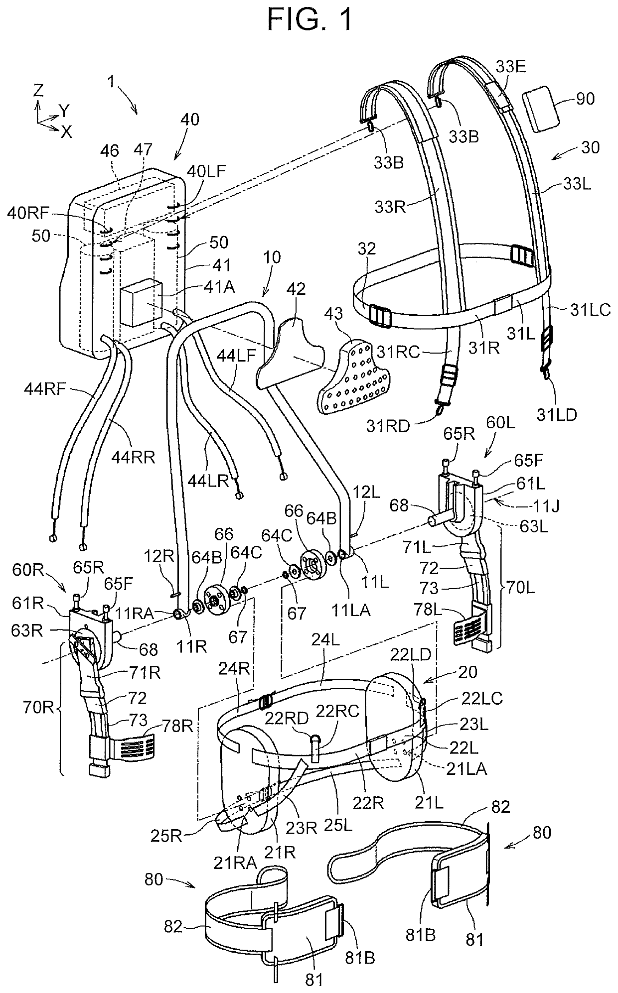
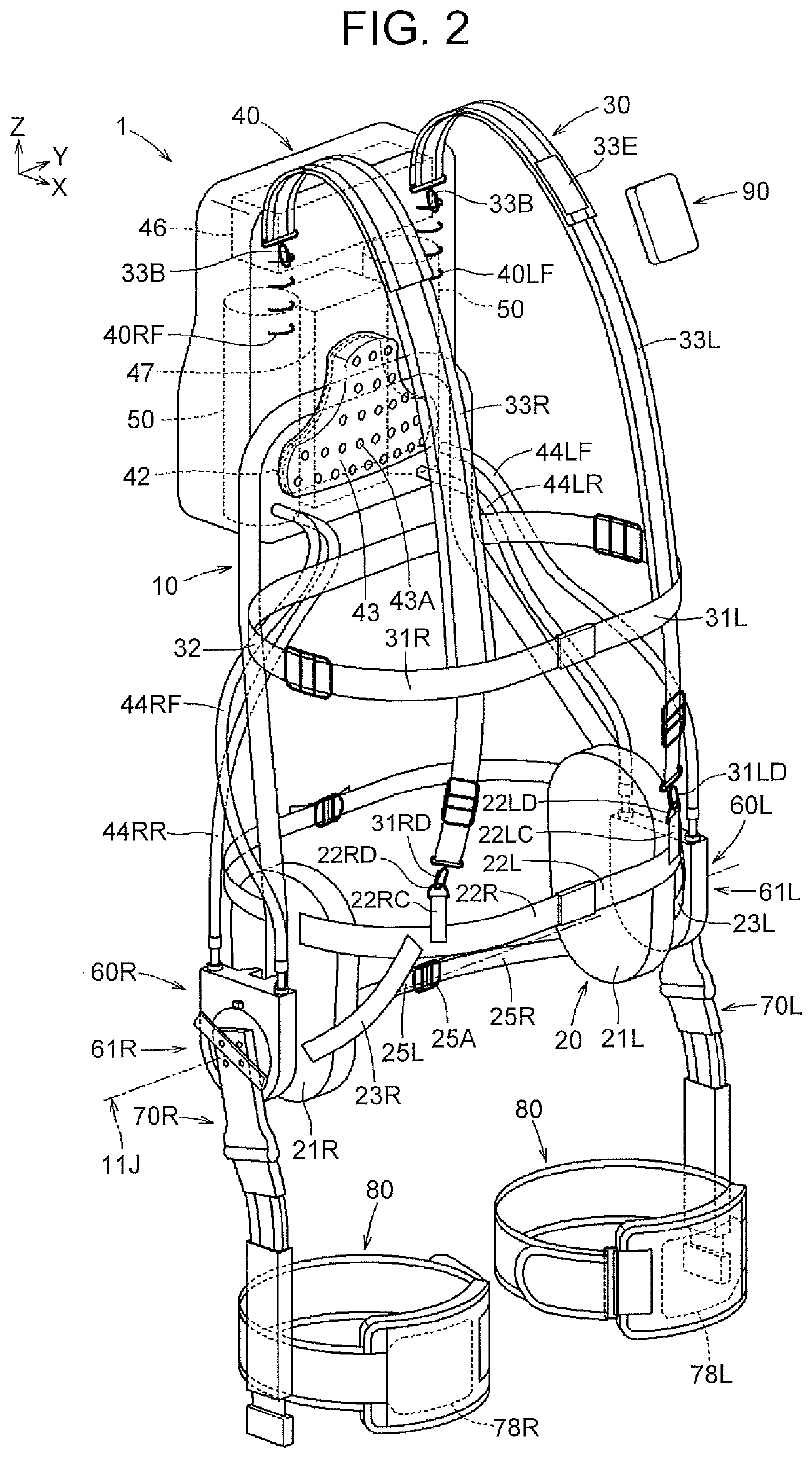
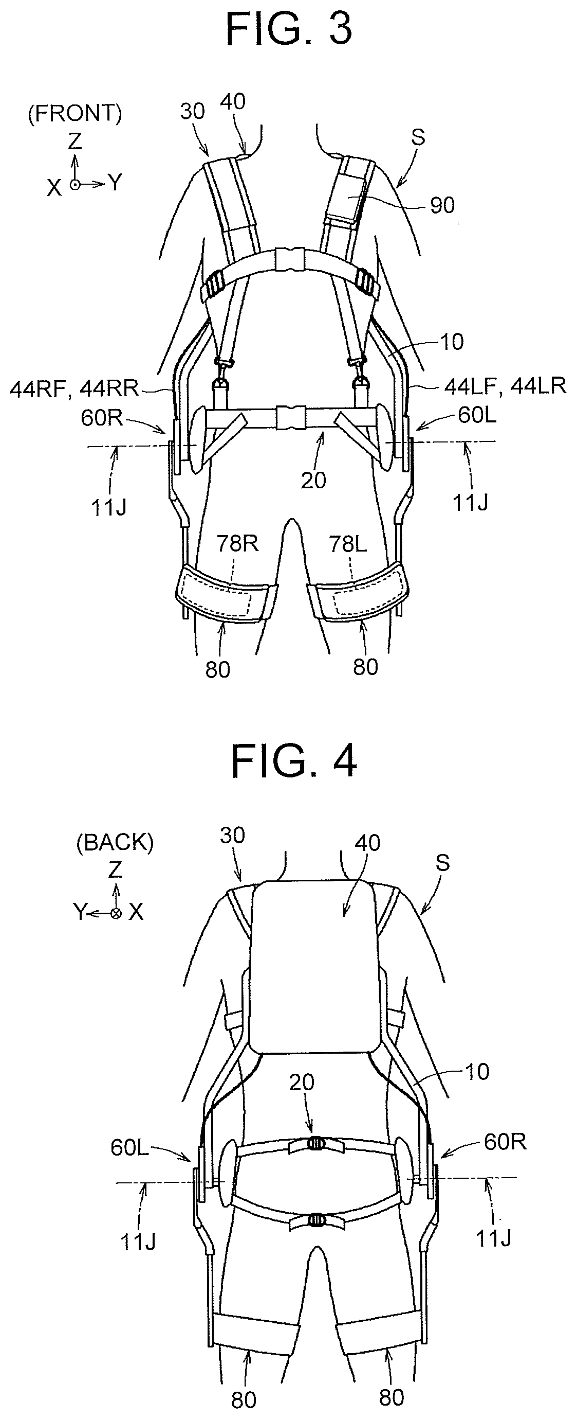
[0054]The structure of a power assist suit 1 (see FIG. 2) will be described below. The power assist suit 1 is a device that assists turning of the thighs relative to the hips (or turning of the hips relative to the thighs) of a wearer when the wearer lifts a load (or puts down a load), or assists swinging of the thighs relative to the hips of the wearer during walking. The X-axis, Y-axis, and Z-axis in the drawings are orthogonal to one another, and as seen from the wearer wearing the power assist suit 1, the X-axis direction, Y-axis direction, and Z-axis direction correspond to a frontward direction, leftward direction, and upward direction, respectively. When the directions of up, down, left, right, front, and back are indicated in the following description, these directions refer to an upward direction (Z-axis direction), downward direction (the opposite direction from the Z-axis direction), leftward direction (Y-axis direction), rightward direction (the opposite direction from t...


PUM


Abstract

A power assist suit includes a harness worn at least around hips of a wearer, an assist unit, a power unit, and a bearing roller. The assist unit includes an arm and a thigh-worn part. A rail is provided at a part of the arm in a longitudinal direction. The rail includes channel-shaped parts extending along the longitudinal direction. The thigh-worn part is connected to sliding movable parts or integrated with at least a portion of the sliding movable parts. The bearing roller is disposed between each of the channel-shaped parts in the rail and each of inner wall surfaces of the sliding movable parts facing the respective channel-shaped parts.

Description

INCORPORATION BY REFERENCE[0001]The disclosure of Japanese Patent Application No. 2018-230918 filed on Dec. 10, 2018 and Japanese Patent Application No. 2018-230920 filed on Dec. 10, 2018, each including the specification, drawings and abstract, is incorporated herein by reference in its entirety.BACKGROUND1. Technical Field[0002]The present disclosure relates to a power assist suit that assists a motion of the thighs relative to the hips of a wearer or a motion of the hips relative to the thighs of the wearer.2. Description of Related Art[0003]In recent years, power assist suits that reduce burden on the hips etc. of wearers are desired at various worksites including manufacturing, distribution, construction, agriculture, nursing-care, and rehabilitation.[0004]One example is the motion assisting device disclosed by Japanese Patent Application Publication No. 2018-149624 (JP 2018-149624 A) that has: a (right) actuator and a (left) actuator disposed respectively on the right hip and ...

Claims


Application Information

Patent Timeline
Patent Type & Authority Applications(United States)
IPC IPC(8): A61H3/00
CPCA61H2201/164A61H2201/1454A61H2201/1614A61H2201/1628A61H3/00A61H2201/1676A61H2201/165A61H2201/1619A61H2201/1623A61H2003/007A61H2201/1664B25J9/0006A61H1/0244A61H2201/1207A61H2201/0196A61H2205/088A61H2230/625A61H2205/108A61H2201/5097A61H2201/0176A61H2201/1215A61H2201/1463A61H2201/5069A61H2201/1652
Inventor KATOH, YOSHINOBUOHTSUBO, KAZUYOSHIOHTA, HIROMICHIKOGUSHI, KENSAKUUMETANI, AKIHISASHIBATA, NOBUAKIKOBAYASHI, YUKI
Owner JTEKT CORP
Why Eureka
Try Eureka