
Injection molding apparatus and injection molding method

a technology of injection molding and injection molding, which is applied in the direction of coatings, etc., can solve the problems of easy generation of large bubbles, product defects on the surface, and product mechanical properties may be affected, and achieve the effect of desirable quality and yield

Inactive Publication Date: 2020-06-11
CHUNG YUAN CHRISTIAN UNIVERSITY
View PDF0 Cites 2 Cited by
  • Summary
  • Abstract
  • Description
  • Claims
  • Application Information

AI Technical Summary

Benefits of technology

The invention provides an injection molding apparatus and method that uses supercritical foaming technology to manufacture products with good quality and yield. The apparatus includes a mold with a movable portion that adjusts the volume of the molding cavity to control the pressure inside. A supercritical fluid is injected into the molding cavity and prevented from being gasified in the pressurized state. After the raw material solidifies, the mold is moved to reduce the pressure inside and the supercritical fluid foams to avoid defects on the surface of the material. The technical effects of the invention are improved quality and yield of the manufactured products.

Problems solved by technology

However, also due to the foaming properties, the product is prone to have defects on the surface.
Besides, because of the difficulty in controlling bubbles in the interior of the product, a large bubble may be generated easily, and the mechanical properties of the product may be affected.
As a result, the product quality and yield are lower than expected.

Method used


Image

  • Injection molding apparatus and injection molding method
  • Injection molding apparatus and injection molding method
  • Injection molding apparatus and injection molding method

Examples


Embodiment Construction

[0024]Reference will now be made in detail to the present preferred embodiments of the invention, examples of which are illustrated in the accompanying drawings. Wherever possible, the same reference numbers are used in the drawings and the description to refer to the same or like parts.

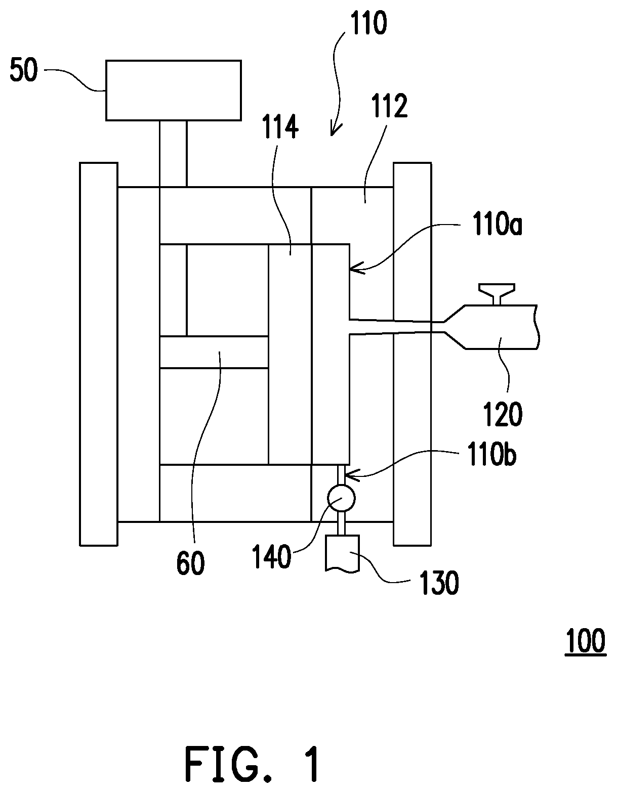
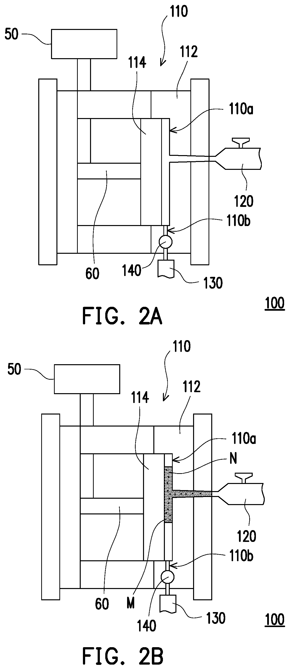
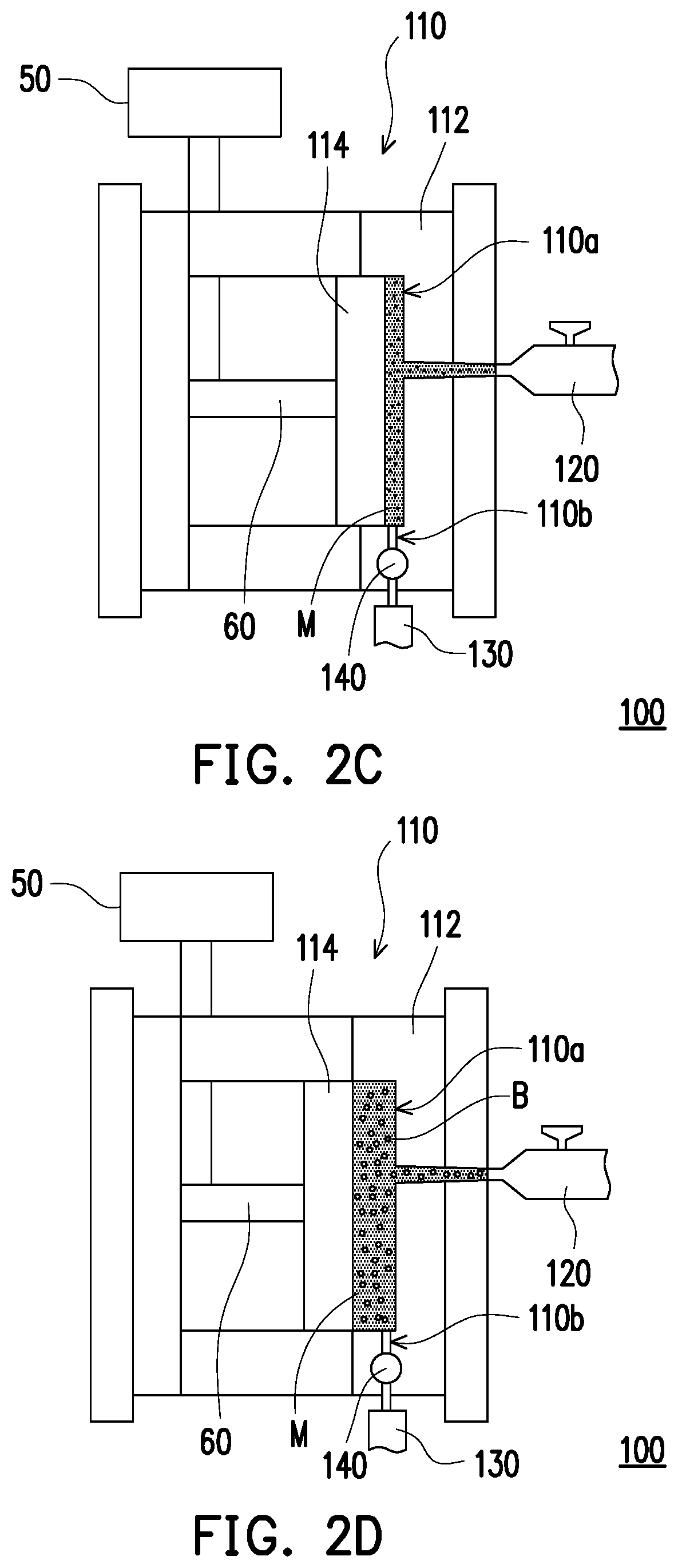
[0025]FIG. 1 is a schematic view illustrating an injection molding apparatus according to an embodiment of the invention. Referring to FIG. 1, an injection molding apparatus 100 of this embodiment includes a mold 110, an injection device 120, and a gas supply device 130. The mold 110 includes a fixed portion 112 and a movable portion 114. A molding cavity 110a is formed between the fixed portion 112 and the movable portion 114. The movable portion 114 is adapted to move relative to the fixed portion 112 to change a volume of the molding cavity 110a.

[0026]The mold 110 has a gas injection passage 110b. The gas injection passage 11b connects the interior of the molding cavity 110a and the exterior of t...


PUM

PropertyMeasurementUnit
volumeaaaaaaaaaa
pressureaaaaaaaaaa
timeaaaaaaaaaa

Abstract

An injection molding apparatus including a mold and an injection device is provided. The mold includes a fixed portion and a movable portion. A molding concavity is formed between the fixed portion and the movable portion, and the movable portion is adapted to move relative to the fixed portion to change a volume of the molding cavity, so that a pressure inside the molding concavity is adjusted between a pressurized state and a non-pressurized state. The injection device is adapted to inject a material into the molding concavity. The material includes a supercritical fluid, the supercritical fluid is prevented from being gasified in the pressurized state, and the supercritical fluid is gasified in the non-pressurized state. In addition, an injection molding method is also provided.

Description

CROSS-REFERENCE TO RELATED APPLICATION[0001]This application claims the priority benefit of Taiwan application serial no. 107143654, filed on Dec. 5, 2018. The entirety of the above-mentioned patent application is hereby incorporated by reference herein and made a part of this specification.BACKGROUND OF THE INVENTION1. Field of the Invention[0002]The invention relates to a molding apparatus and a molding method, and particularly relates to an injection molding apparatus and an injection molding method.2. Description of Related Art[0003]Owing to the foaming properties, the products manufactured through the supercritical foaming technology exhibit properties such as a high weight loss ratio, high impact strength, and high elasticity, etc., and have therefore been applied to various fields. However, also due to the foaming properties, the product is prone to have defects on the surface. Besides, because of the difficulty in controlling bubbles in the interior of the product, a large b...

Claims


Application Information

Patent Timeline
Patent Type & Authority Applications(United States)
IPC IPC(8): B29C45/56B29C45/00B29C45/17
CPCB29C45/174B29C45/0025B29C45/56B29C44/02B29C44/42B29C44/586B29C44/3496
Inventor CHEN, SHIA-CHUNGCHANG, YUNG-HSIANGLEE, KUAN-HUACHANG, CHE-WEITSAI, PI-LIN
Owner CHUNG YUAN CHRISTIAN UNIVERSITY
Learn More