Observation apparatus, observation method, and observation program

Inactive Publication Date: 2020-06-18
FUJIFILM CORP
View PDF1 Cites 0 Cited by
  • Summary
  • Abstract
  • Description
  • Claims
  • Application Information

AI Technical Summary

Benefits of technology

[0020]According to the technology of the disclosure, the control unit corrects the imaging position in a case where the partial image scheduled to be subsequently captured is captured based on the reference shape information of the container stored in the storage unit and the partial shape information calculated by the calculation unit, and causes the series of partial images in which the adjacent partial images are consistent to be captured based on the corrected imaging position. Since the imaging position of the imaging unit is appropriately corrected during acquisition of the series of partial images and the movement unit and the imaging unit are controlled, re-imaging after the end of a series of imaging or re-imaging of the partial images at the same position by suspending the series of imaging does not occur. Consequently, re-imaging is not necessary, and consistent adjacent partial images can be acquired.

Problems solved by technology

However, in the technology disclosed in JP2016-125913A, imaging has to be performed again each time a defect occurs in a part of the tile images.

Method used


Image

  • Observation apparatus, observation method, and observation program
  • Observation apparatus, observation method, and observation program
  • Observation apparatus, observation method, and observation program

Examples


Embodiment Construction

[0032]Hereinafter, one example of an embodiment according to the technology of the disclosure will be described with reference to the drawings. The same or equivalent constituents and parts in each drawing will be designated by the same reference signs. Dimensional ratios in the drawings are exaggerated for convenience of description and may be different from the actual ratios.

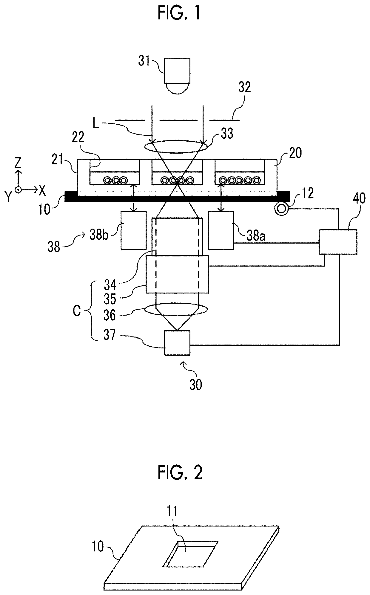
[0033]FIG. 1 is a diagram illustrating a schematic configuration of an observation apparatus according to the embodiment of the technology of the disclosure. FIG. 2 is a diagram illustrating one example of a placing stand.

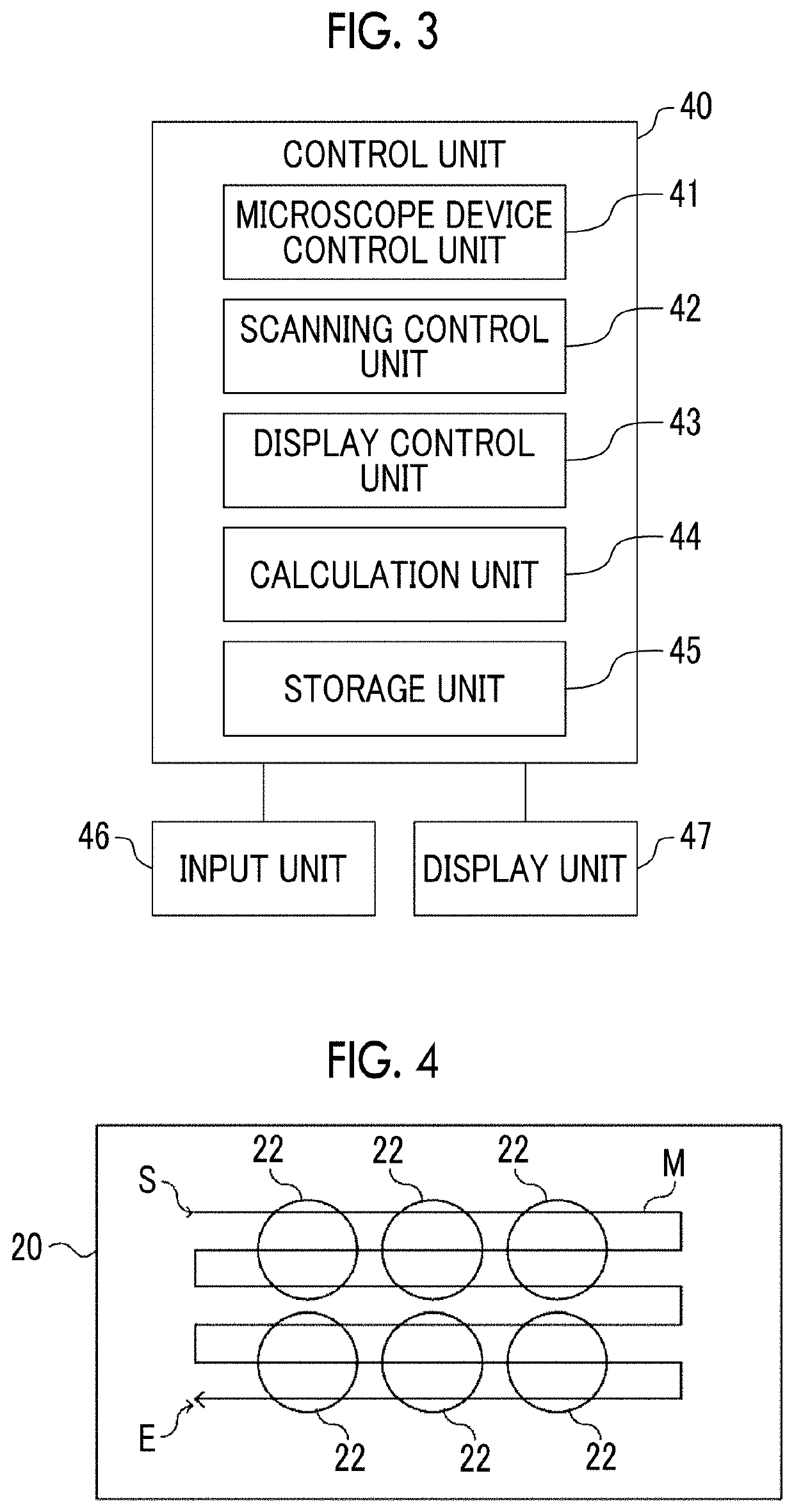
[0034]The observation apparatus is an apparatus for observing an observation target accommodated in a cultivation container 20 placed on a placing stand 10 by a microscope device 30. The placing stand 10 and the microscope device 30 are controlled by a control unit 40. Each configuration will be described in order.

[0035]The placing stand 10 is a stage on which the cultivation container 20 can...


PUM


Abstract

An observation apparatus includes an imaging unit that images a container accommodating an observation target in an accommodation part and the observation target in a field of view smaller than the accommodation part at predetermined imaging positions and acquires a series of partial images, a movement unit that relatively moves at least one of the container or the imaging unit with respect to the other, a calculation unit that calculates partial shape information representing a partial shape of the container from the partial image obtained by imaging performed by the imaging unit, a storage unit that stores reference shape information representing a shape of the container, and a control unit that corrects the imaging position in a case where the partial image scheduled to be subsequently captured during acquisition of the series of partial images is captured based on the partial shape information and the reference shape information, and causes the imaging unit to perform imaging based on the corrected imaging position.

Description

CROSS-REFERENCE TO RELATED APPLICATIONS[0001]This application is a Continuation of PCT International Application No. PCT / JP2018 / 031777 filed on Aug. 28, 2018, which claims priority under 35 U.S.C § 119(a) to Japanese Patent Application No. 2017-186414 filed on Sep. 27, 2017. Each of the above application(s) is hereby expressly incorporated by reference, in its entirety, into the present application.BACKGROUND OF THE INVENTION1. Field of the Invention[0002]The technology of the disclosure relates to an observation apparatus, an observation method, and an observation program for observing an observation target by relatively moving at least one of a container accommodating the observation target or an imaging unit with respect to the other.2. Description of the Related Art[0003]In recent years, various technologies for imaging a subject such as various cells and analyzing an acquired image have been suggested. For example, a method of imaging a pluripotent stem cell such as an embryoni...

Claims


Application Information

Patent Timeline
Patent Type & Authority Applications(United States)
IPC IPC(8): G02B21/36G02B21/26G02B21/24G06T7/55
CPCG02B21/26G06T7/55G02B21/365G06T2207/10056G02B21/245C12M1/34G01N21/17G06T2207/10016G06T7/33G06T2200/32G06T2207/30024G02B21/34G02B21/14G02B21/367
Inventor MATSUBARA, KENTA
Owner FUJIFILM CORP
Why Eureka
Try Eureka