Winding inductor component

Active Publication Date: 2020-06-18
MURATA MFG CO LTD
View PDF0 Cites 0 Cited by
  • Summary
  • Abstract
  • Description
  • Claims
  • Application Information

AI Technical Summary

Benefits of technology

[0007]With the above embodiment, since the terminal electrodes are non-magnetic bodies, it is possible to suppress reaction of t

Problems solved by technology

However, since nickel is a magnetic material, when the winding inductor component including the terminal electrodes containing nickel is used in an environment of a strong magnetic field, there is a problem that nickel reacts with the magnetic field to disturb the surrounding magnetic field.
For example, when the winding inductor component is used in MRI

Method used


Image

  • Winding inductor component
  • Winding inductor component
  • Winding inductor component

Examples


Embodiment Construction

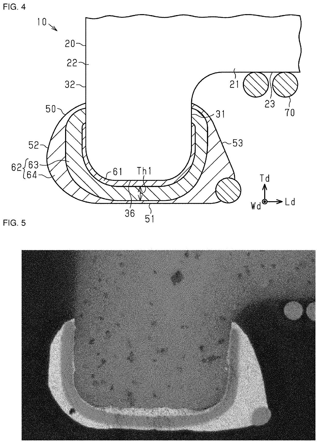
[0019]Hereinafter, an embodiment of a winding inductor component will be described. It should be noted that components in the accompanying drawings may be enlarged in order to facilitate understanding. Dimensional ratios of the components may be different from actual ones or different from those in the other figures. Although hatching is applied in the cross-sectional view, hatching of some components may be omitted in order to facilitate understanding.

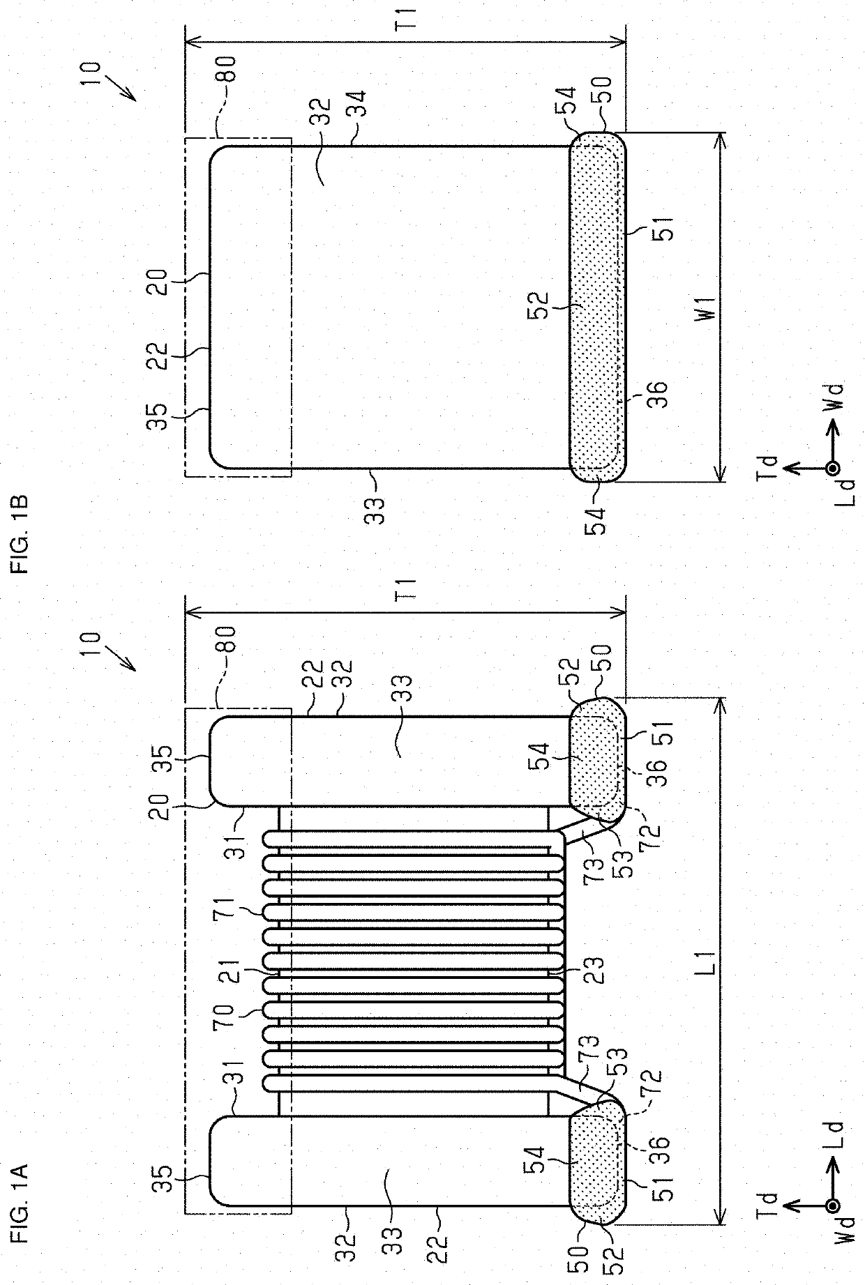
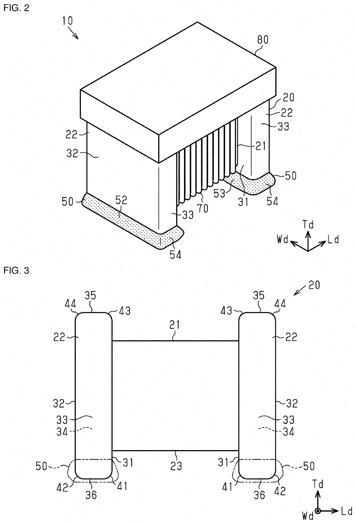
[0020]A winding inductor component 10 (hereinafter, referred to as inductor component 10) illustrated in FIGS. 1A, 1B and 2 is a surface mount-type winding inductor component that is mounted on a circuit board or the like, for example. The inductor component 10 may be used in a circuit (high-frequency circuit or the like) provided in an inspection apparatus such as MRI (magnetic resonance imaging), for example, and can be used in various apparatuses.

[0021]The inductor component 10 includes a core 20 having a columnar shaft portion 21 ...


PUM


Abstract

A winding inductor component includes a core having a columnar shaft portion and a pair of support portions provided at both ends of the shaft portion. The wiring inductor component further includes terminal electrodes provided on the pair of support portions, respectively, and being non-magnetic bodies, and a wire wound around the shaft portion and having both end portions connected to the terminal electrodes of the pair of support portions.

Description

CROSS-REFERENCE TO RELATED APPLICATION[0001]This application claims benefit of priority to Japanese Patent Application No. 2018-235718, filed Dec. 17, 2018, the entire content of which is incorporated herein by reference.BACKGROUNDTechnical Field[0002]The present disclosure relates to a winding inductor component having a wire wound around a core.Background Art[0003]In the past, various types of inductor components have been mounted on electronic apparatuses. The winding inductor component has a core and a wire wound around the core. End portions of the wire are connected to terminal electrodes provided on the core. Normally, the end portions of the wire are thermally compression bonded to the terminal electrodes by using a heater tip as described in, for example, Japanese Unexamined Patent Application Publication No. 10-312922, from a viewpoint of manufacturing cost. In order to prevent the terminal electrodes from being molten at the time of the thermal compression bonding, the te...

Claims


Application Information

Patent Timeline
IPC IPC(8): H01F27/29H01F27/28H01F17/04
CPCH01F27/2828H01F27/292H01F17/045H01F27/29H01F27/24H01F27/36
Inventor TANAKA, AKIRA
Owner MURATA MFG CO LTD
Why Eureka
Try Eureka