Solid electrolytic capacitor

Pending Publication Date: 2021-10-28
NIPPON CHIMI CON CORP
View PDF0 Cites 0 Cited by
  • Summary
  • Abstract
  • Description
  • Claims
  • Application Information

AI Technical Summary

Benefits of technology

[0030]According to the present disclosure, the solid electrolytic capacitor using the combination of the solid electrolyte and the liquid can suppress the dedoping reactio

Problems solved by technology

However, compared to a liquid electrolytic capacitor in which the capacitor element is impregnated with the electrolytic solution and which does not have the solid electrolyte laye

Method used


Image

  • Solid electrolytic capacitor
  • Solid electrolytic capacitor
  • Solid electrolytic capacitor

Examples


Example

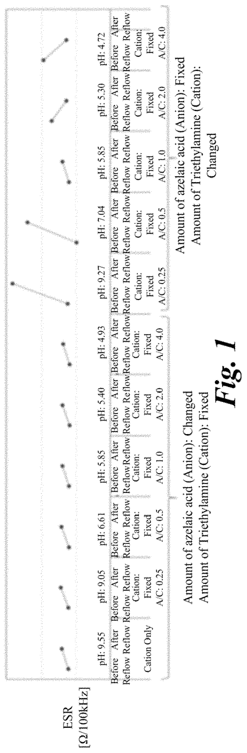
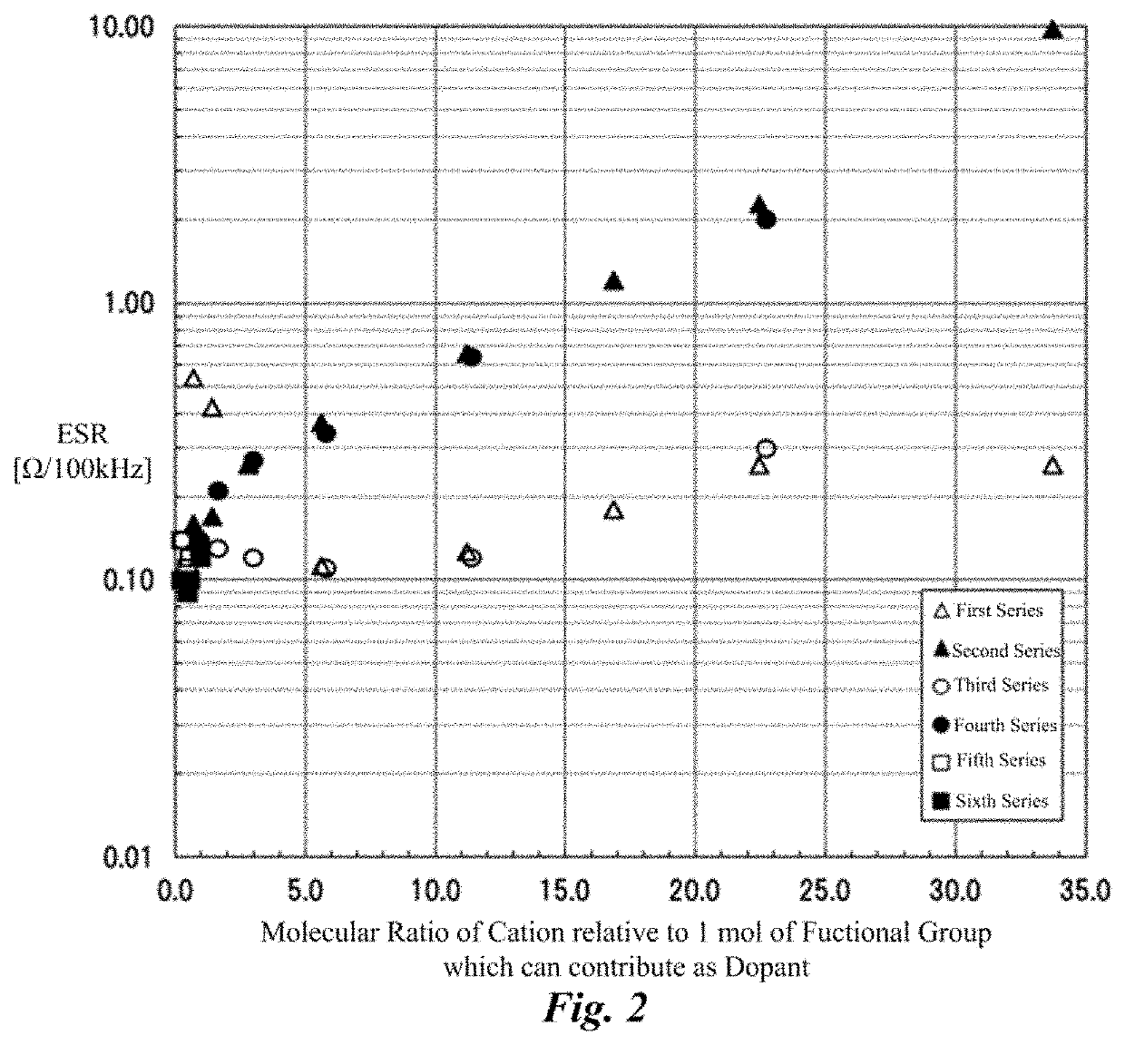
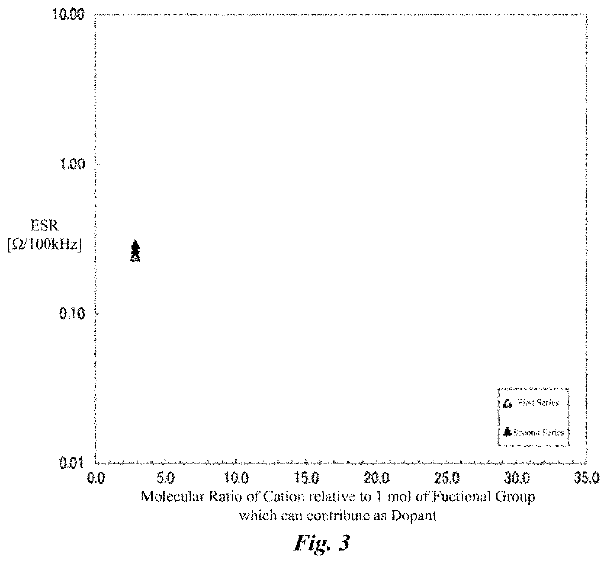
[0080]Solid electrolytic capacitors of examples 1 to and comparative example 1 were produced by changing amounts of the cation components and the anion components in the electrolyte layer, and the loading of heat stress by the reflow process was given to the examples, and the ESR before and after the loading of heat stress was measured. Common points among each solid electrolytic capacitor were as follows.

[0081]That is, the anode foil was an aluminum foil, the surface thereof was enlarged by the etching process, and the dielectric oxide film was formed thereon by the chemical treatment. The cathode foil was a plane foil that is an aluminum foil to which the etching process had not been performed. The lead wires were connected to the anode foil and the cathode foil, respectively, and the anode foil and the cathode foil were set to face each other and were wound via the manila separator. In this way, the capacitor element with diameter of 6.1 mm×height of 6.3 mm was formed. This capac...

Example

[0086]As shown in Table 1, as for examples 1 to 7 and comparative example 1, the cation component was not added to the solid electrolyte layer, the amount of azelaic acid that is the anion components in the liquid was fixed, and the amount of ammonia that is the cation components in the liquid was changed from few to equivalent and then to excessive, relative to the amount of anion components. In examples 8 to 10, the cation component was not added to the solid electrolyte layer, the amount of ammonia in the liquid was fixed, and the amount of anion components in the liquid was changed from non-present to excessive, relative to the amount of ammonia. In examples 11 to 17, the amount of ammonia that is the cation component in the solid electrolyte layer was fixed, the amount of anion components in the liquid was fixed, and the amount of ammonia that is the cation components in the liquid was changed from non-present to equivalent and then to excessive, relative to the amount of anion...

Example

[0106]As shown in Table 5, the solid electrolytic capacitor of comparative example 5, examples 40 to 48, and example 4 had different molar fraction of the cation component in the liquid. That is, the molar fraction of triethylamine and ammonia was changed by each 0.1 between the solid electrolytic capacitor of comparative example 1 in which the molar fraction of triethylamine was 1, and the solid electrolytic capacitor of example 4 in which the molar fraction of ammonia was 1. The solid electrolytic capacitor of comparative example 5 and examples 40 to 48 were produced by the same condition as example 4 except for this molecular fraction.

[0107]FIG. 6 is a graph illustrating a relationship between ESR after the reflow, and a molar fraction of ammonia in all the cation components included in the electrolytic solution (liquid) based on Table 5. As understood from Table 5 and FIG. 6, it was found that ESR after the loading of heat stress can be suppressed low as long as ammonia was incl...


PUM


Abstract

In a solid electrolytic capacitor having an electrolyte layer consisting of a solid electrolyte layer and a liquid, the solid electrolytic capacitor, which suppresses a dedoping reaction and which ESR thereof does not keenly increase, in particular, after a loading of heat stress, is provided. In the solid electrolytic capacitor, the electrolyte layer is formed in the capacitor element which is formed by opposing an anode foil and a cathode foil. This electrolyte layer includes the solid electrolyte layer and the liquid. The solid electrolyte layer includes a conductive polymer consisting of a dopant and a conjugated polymer. The liquid is filled in air gaps in the capacitor element on which the solid electrolyte layer is formed. The electrolyte layer includes ammonia as a cation component, and a molecular ratio of the cation component relative to 1 mol of a functional group which can contribute to a doping reaction of the dopant, in the electrolyte layer is 23 or less.

Description

FIELD OF INVENTION[0001]The present disclosure relates to a solid electrolytic capacitor.BACKGROUND[0002]In electrolytic capacitors utilizing valve action metal such as tantalum and aluminum, etc., by making the valve action metal as the anode electrode into shapes of a sintered body or an etching foil, etc., to enlarge the surface of dielectric, the electrolytic capacitors can be in a small size and have a large capacity. In particular, a solid electrolyte capacitor in which the dielectric oxide film is covered by the solid electrolyte is in a small size, has a large capacity, is a low equivalent series resistor, and is required for downsizing, high functionality, and reducing cost thereof.[0003]As solid electrolytes, manganese dioxide, 7,7,8,8-tetracyanoquinodimetane (TCNQ) complex, etc., are known. In recent years, conductive polymers which are derived from monomers having n conjugated double bonds, such as poly(3,4-ethylenedioxythiophene) which has slow reaction speed and which ...

Claims


Application Information

Patent Timeline
IPC IPC(8): H01G9/028H01G9/15H01G9/052
CPCH01G9/028H01G9/052H01G9/15H01G9/035H01G9/145H01G9/0036H01G9/0029
Inventor SATO, KENTASAKAKURA, MASAO
Owner NIPPON CHIMI CON CORP
Why Eureka
Try Eureka