
Positive Electrode Active Material for Lithium Secondary Battery and Method for Producing the Same

Pending Publication Date: 2022-11-17
LG ENERGY SOLUTION LTD
View PDF0 Cites 0 Cited by
  • Summary
  • Abstract
  • Description
  • Claims
  • Application Information

AI Technical Summary

Benefits of technology

The patent is about a way to improve the performance of batteries by creating a specific coating layer on the surface of a certain material. This coating helps to prevent the material from reacting too much with the battery's electrolyte solution, which could cause damage and reduce the battery's efficiency and capacity. This technology can be applied to batteries that are used in high-temperature cycles.

Problems solved by technology

However, LiCoO2 has very poor in thermal properties due to the destabilization of a crystal structure according to de-lithium, and is also expensive.
Therefore, LiCoO2 has a limitation in being used as a power source in a field such as an electric vehicle or the like in a large amount.
The lithium transition metal oxide has a problem in that a transition metal is eluted due to HF formed by a reaction with an electrolyte solution during charge / discharge at a high temperature, and thus, performance is rapidly degraded.

Method used


Image

  • Positive Electrode Active Material for Lithium Secondary Battery and Method for Producing the Same
  • Positive Electrode Active Material for Lithium Secondary Battery and Method for Producing the Same
  • Positive Electrode Active Material for Lithium Secondary Battery and Method for Producing the Same

Examples


example 1

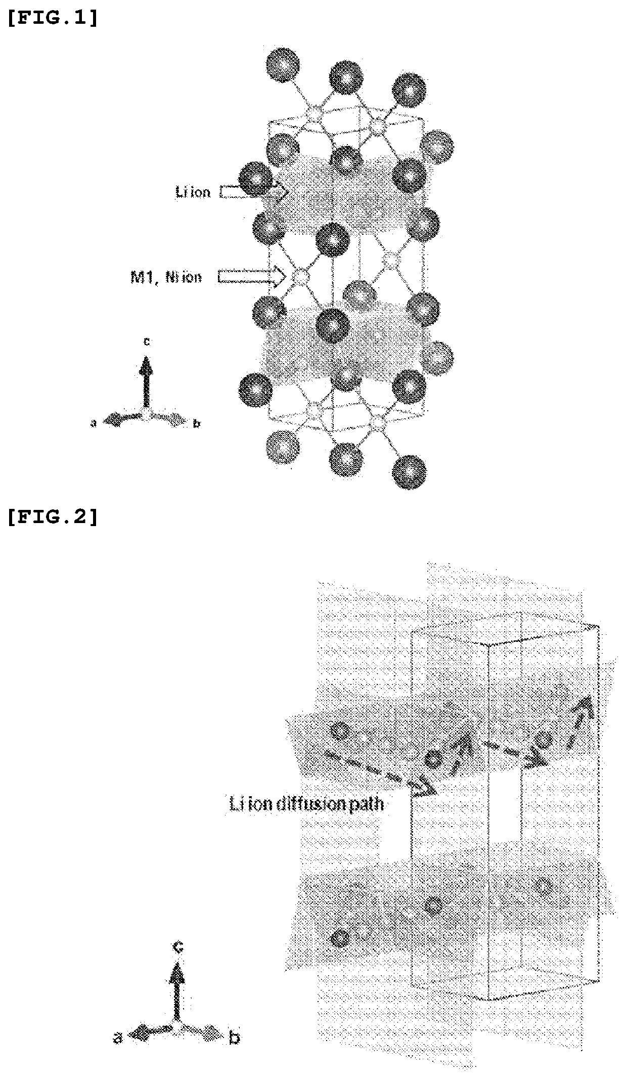
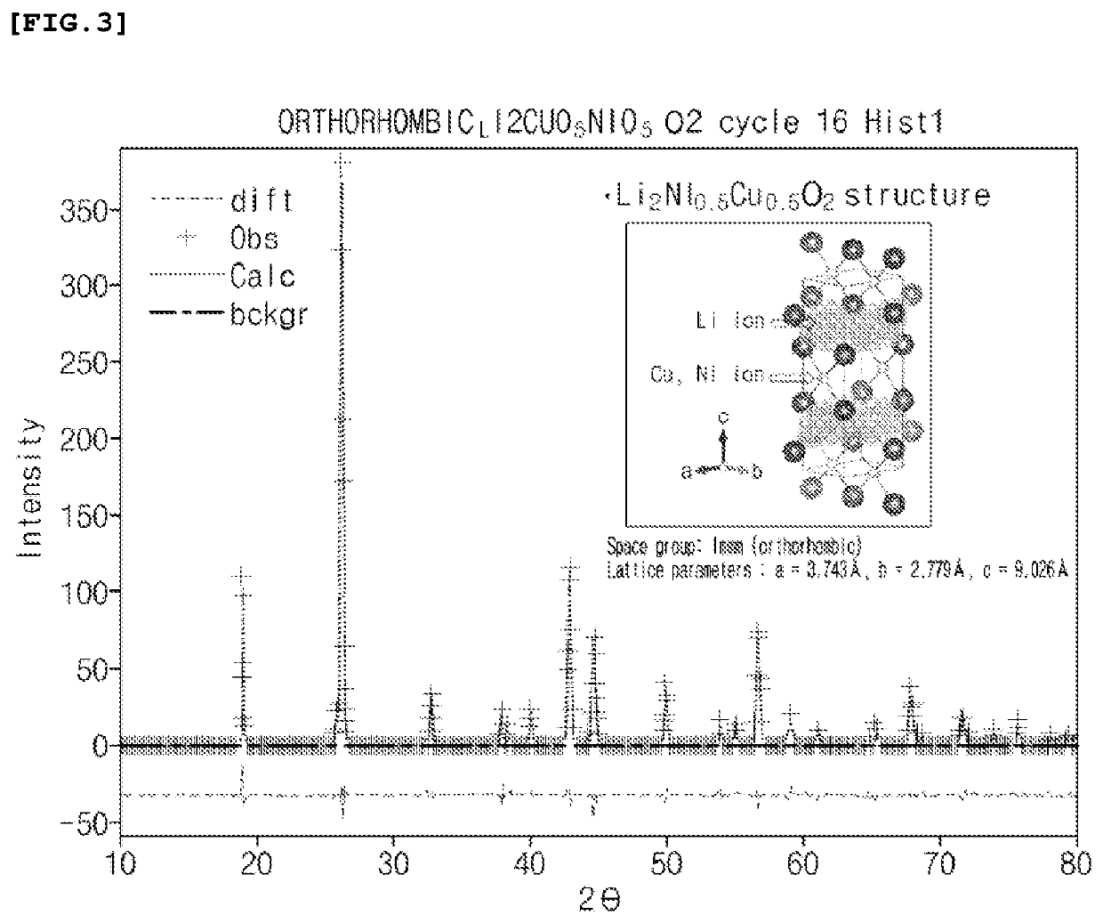
[0102]A transition metal hydrate [Ni0.5Cu0.5](OH)2 was synthesized by a co-precipitation method. Specifically, nickel nitrate and copper nitrate were dissolved in water in a molar ratio of Ni:Cu of 1:1 to prepare a nitrate aqueous solution of 1.5 M. Next, while stirring the nitrate aqueous solution, 28% ammonia was dropped by 1 molar equivalent to adjust pH, and LiOH was added thereto by 2 molar equivalents to adjust a final pH to be 12. Next, the aqueous solution was stirred while being heat-treated for 3 hours at 50° C., and a precipitate was washed, and then recovered by centrifugation. Next, the precipitate was dried at 75° C., and then heat-treated for 6 hours at 450° C. in an air atmosphere. The heat-treatment product was mixed with LiOH.H2O, roll-pressed into a pellet form, and then heat-treated for 12 hours at 800° C. in an argon atmosphere to obtain oxide powder. In order to compensate for the loss of lithium at a high temperature, Li in 5% excess with respect to the oxide ...

experimental example 2

y Measurement

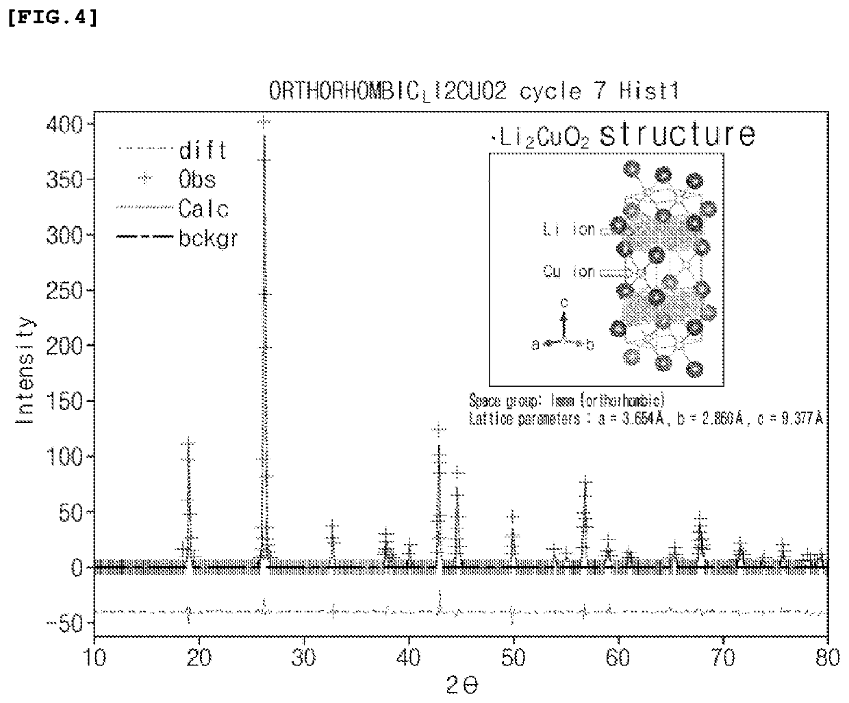
[0108]The oxygen formation energy of each of the materials for forming a coating layer prepared by Example 1 and Comparative Examples 1 and 2 was confirmed. Specifically, using a Vienna Ab-initio simulation package (VASP) program, a density functional theory (DFT) calculation method was applied to calculate oxygen formation energy according to changes in crystal structure, and the calculation results are shown in Table 1 below. At this time, the oxygen formation energy was calculated under the following conditions, based on the DFT, and PBE functional PAW_PBE pseudopotential.

[0109]Hubbard U term for Ni=6.2 eV

[0110]Cut-off energy: 520 eV

[0111]Calculation model: A super cell with Li48 (Ni and / or Cu)24O48 atoms

[0112]Oxygen vacancy (V0) generation density=1 / 48 (˜2.1at. %), based on calculated values for O2 gas (O-rich environment)

TABLE 1Oxygen formationStructureenergy (V0) (eV)Example 1Li2 (Ni0.5Cu0.5) O2 3.42(Immm)ComparativeLi2CuO2 (Immm)2.82Example 1ComparativeLi2NiO2 (I...


PUM


Abstract

A positive electrode active material includes a lithium transition metal oxide having a spinel crystal structure, and a coating layer positioned on the surface of the lithium transition metal oxide, wherein the coating layer has an orthorhombic structure, and includes an oxide represented by Formula 1. A method for producing the positive electrode active material, a positive electrode including the positive electrode active material, and a lithium secondary battery, the positive electrode active material.

Description

CROSS-REFERENCE TO RELATED APPLICATIONS[0001]This application is a national phase entry under 35 U.S.C. § 371 of International Application No. PCT / KR2020 / 015925, filed on Nov. 12, 2020, which claims the benefit of Korean Patent Application No. 10-2019-0145386, filed on Nov. 13, 2019, in the Korean Intellectual Property Office, the disclosures of which are incorporated herein in its entirety by reference.TECHNICAL FIELD[0002]The present invention relates to a positive electrode active material for a lithium secondary battery, a method for producing the positive electrode active material, a positive electrode for a lithium secondary battery including the positive electrode active material, and a lithium secondary battery.BACKGROUND ART[0003]As technology development and demand for mobile devices have increased, the demand for secondary batteries as an energy source has been rapidly increased. Among such secondary batteries, lithium secondary batteries having high energy density and vo...

Claims


Application Information

Patent Timeline
IPC IPC(8): C01G53/00
CPCC01G53/42C01P2002/32C01P2006/40H01M4/505H01M4/62Y02E60/10C01P2002/77C01P2002/76C01P2004/80C01P2002/72H01M4/366H01M10/052C01G45/1242
Inventor LIM, SUNG CHULJANG, MIN CHULKIM, IL HONGUHM, IN SUNGJUNG, BYOUNG HYO
Owner LG ENERGY SOLUTION LTD
Learn More