Monitoring material processing using imaging signal density determined from inline coherent imaging (ICI)

a technology of coherent imaging and imaging signal density, which is applied in the direction of mechanical measurement arrangement, instruments, manufacturing tools, etc., can solve the problems of unstable data, defect-free laser welds of all types, and less effective full-penetration weld process,

Active Publication Date: 2020-06-25
IPG PHOTONICS CORP
View PDF0 Cites 11 Cited by
  • Summary
  • Abstract
  • Description
  • Claims
  • Application Information

AI Technical Summary

Problems solved by technology

Laser welds of all types often contain defects due to process parameters being out of tolerance, variations in input feedstock, or natural fluctuations or instabilities in the melt pool and vapor channel or keyhole.
ICI is very effective for detection of defects in blind / partial penetration vapor channels but has been less effective for full-penetration weld processes.
ICI is normally used to measure the optical path length to the backscattering interface (e.g., keyhole bottom), resulting in unstable data when the keyhole fully penetrates the material.
Certain laser welding techniques present unique challenges when monitoring with ICI.
When monitoring wobble welding with ICI, aligning an imaging beam with the keyhole, phase change region (PCR) or other workpiece sub-region presents challenges because the process beam is moving in a wobble pattern.

Method used


Image

  • Monitoring material processing using imaging signal density determined from inline coherent imaging (ICI)
  • Monitoring material processing using imaging signal density determined from inline coherent imaging (ICI)
  • Monitoring material processing using imaging signal density determined from inline coherent imaging (ICI)

Examples


Embodiment Construction

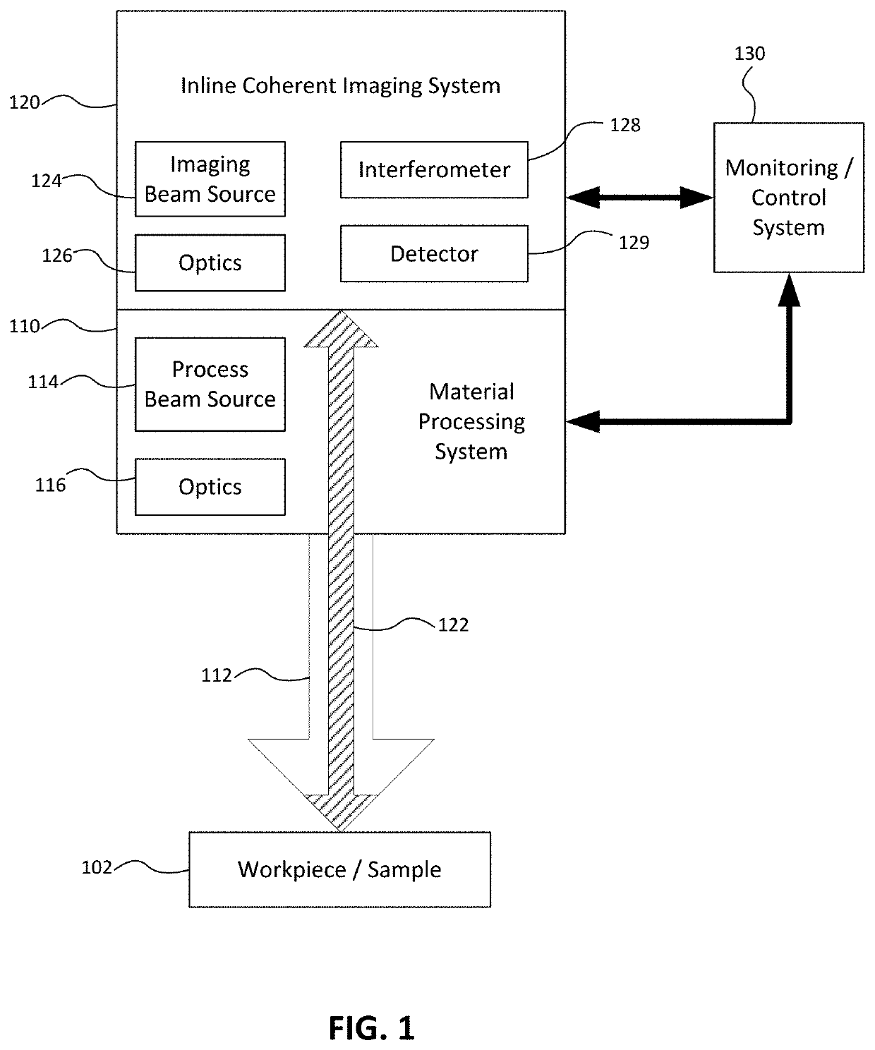
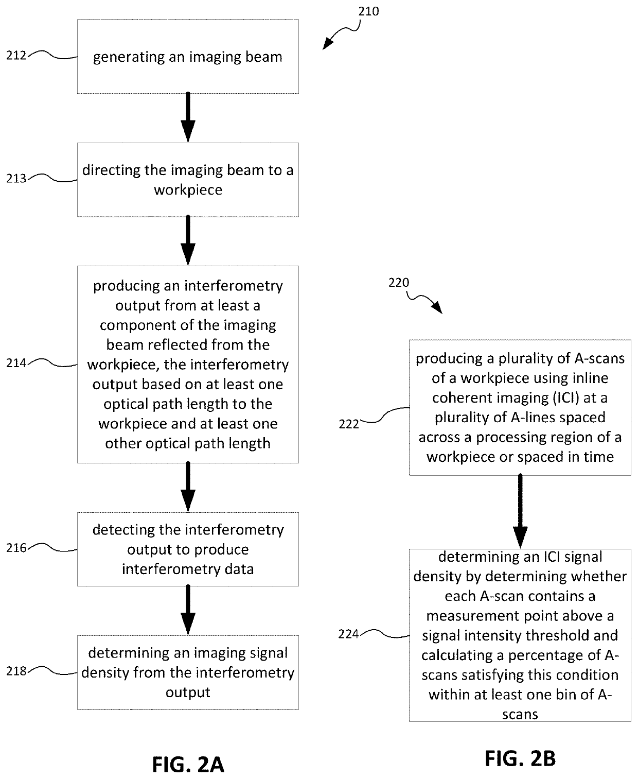
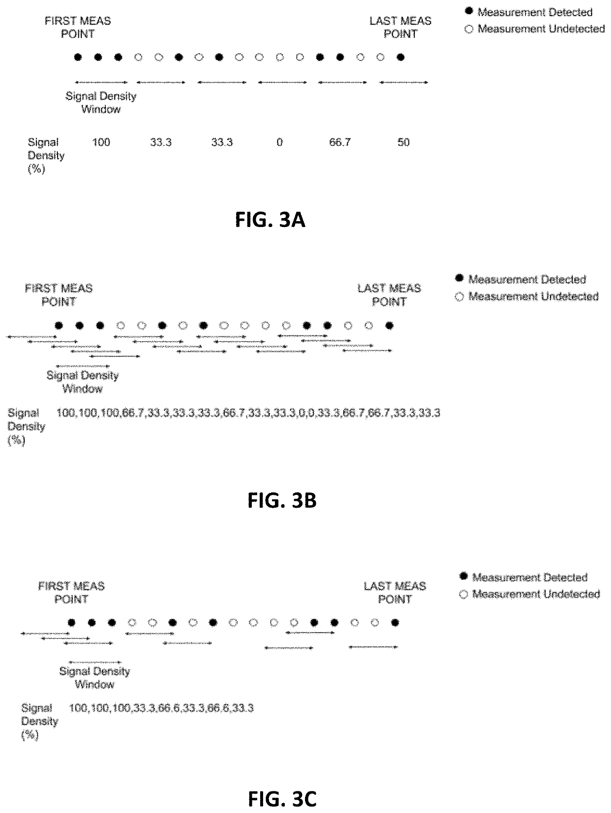
[0030]Systems, methods and apparatuses, consistent with the present disclosure, are used for monitoring material processing using imaging signal density calculated for an imaging beam directed to a workpiece or processing region, for example, during inline coherent imaging (ICI). The imaging signal density may be used, for example, to monitor laser and e-beam welding processes such as full or partial penetration welding performed using pulsed welding, spot welding and / or wobble welding. In some examples, the imaging signal density is indicative of weld penetration as a result of reflections from a keyhole floor and / or from a subsurface structure beneath the keyhole. The monitoring may include automated pass / fail or quality assessment of the welding or material processing or parts produced thereby. The imaging signal density may also be used to control the welding or material processing and / or the monitoring, for example, using an imaging signal density data output as feedback. The i...


PUM

PropertyMeasurementUnit
beam angleaaaaaaaaaa
scan angleaaaaaaaaaa
lengthaaaaaaaaaa

Abstract

Systems, methods and apparatuses are used for monitoring material processing using imaging signal density calculated for an imaging beam directed to a workpiece or processing region, for example, during inline coherent imaging (ICI). The imaging signal density may be used, for example, to monitor laser and e-beam welding processes such as full or partial penetration welding. In some examples, the imaging signal density is indicative of weld penetration as a result of reflections from a keyhole floor and / or from a subsurface structure beneath the keyhole. The monitoring may include, for example, automated pass / fail or quality assessment of the welding or material processing or parts produced thereby. The imaging signal density may also be used to control the welding or material processing, for example, using imaging signal density data as feedback. The imaging signal density may be used alone or together with other measurements or metrics, such as distance or depth measurements.

Description

RELATED APPLICATIONS[0001]The present application claims the benefit of U.S. Provisional Application Ser. No. 62 / 782,071 filed Dec. 19, 2018, which is fully incorporated herein by reference.TECHNICAL FIELD[0002]The present disclosure relates to monitoring material processing and more particularly, to monitoring material processing using imaging signal density determined from inline coherent imaging (ICI).BACKGROUND INFORMATION[0003]Inline coherent imaging (ICI) may be used to monitor various types of processes by detecting reflections from a workpiece inline with a process beam directed to the workpiece. ICI generally involves directing an imaging beam along with the processing beam toward a workpiece and using an interferometer to receive reflections of the imaging beam and produce an output indicative of characteristics of the process and / or workpiece, such as welding keyhole depth. Examples of ICI are described in greater detail in U.S. Pat. Nos. 8,822,875, 9,757,817 and 10,124,4...

Claims


Application Information

Patent Timeline
Patent Type & Authority Applications(United States)
IPC IPC(8): B23K26/03B23K31/12G01B9/02B23K26/082
CPCB23K26/082B23K26/032B23K31/125G01B9/0201G01B9/02014B23K26/24G01B9/02G07C3/146G01B5/0037G01B11/02B23K26/20G01N21/84
Inventor GALBRAITH, CHRISTOPHER M.KANKO, JORDANWEBSTER, PAUL J.L.VAN VLACK, COLEHAYES, GENEVIEVE ELIZABETH
Owner IPG PHOTONICS CORP
Why Eureka
Try Eureka