Reverse Tram Interlock

Active Publication Date: 2020-06-25
TORO CO THE
View PDF0 Cites 0 Cited by
  • Summary
  • Abstract
  • Description
  • Claims
  • Application Information

AI Technical Summary

Benefits of technology

[0005]The present application overcomes the slow movement by allowing the trencher to move in a forward direction at a much faster speed when the blade is disengaged and the trencher is in “transporting” mode. Interlocks are provided that limit the reverse movement of the traction levers so that when the machine is moving with the tr

Problems solved by technology

Sometimes trenching is done a fair distance away from the vehicle that transports the trencher and this

Method used


Image

  • Reverse Tram Interlock
  • Reverse Tram Interlock
  • Reverse Tram Interlock

Examples


Example

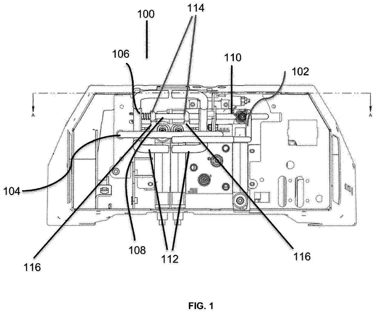
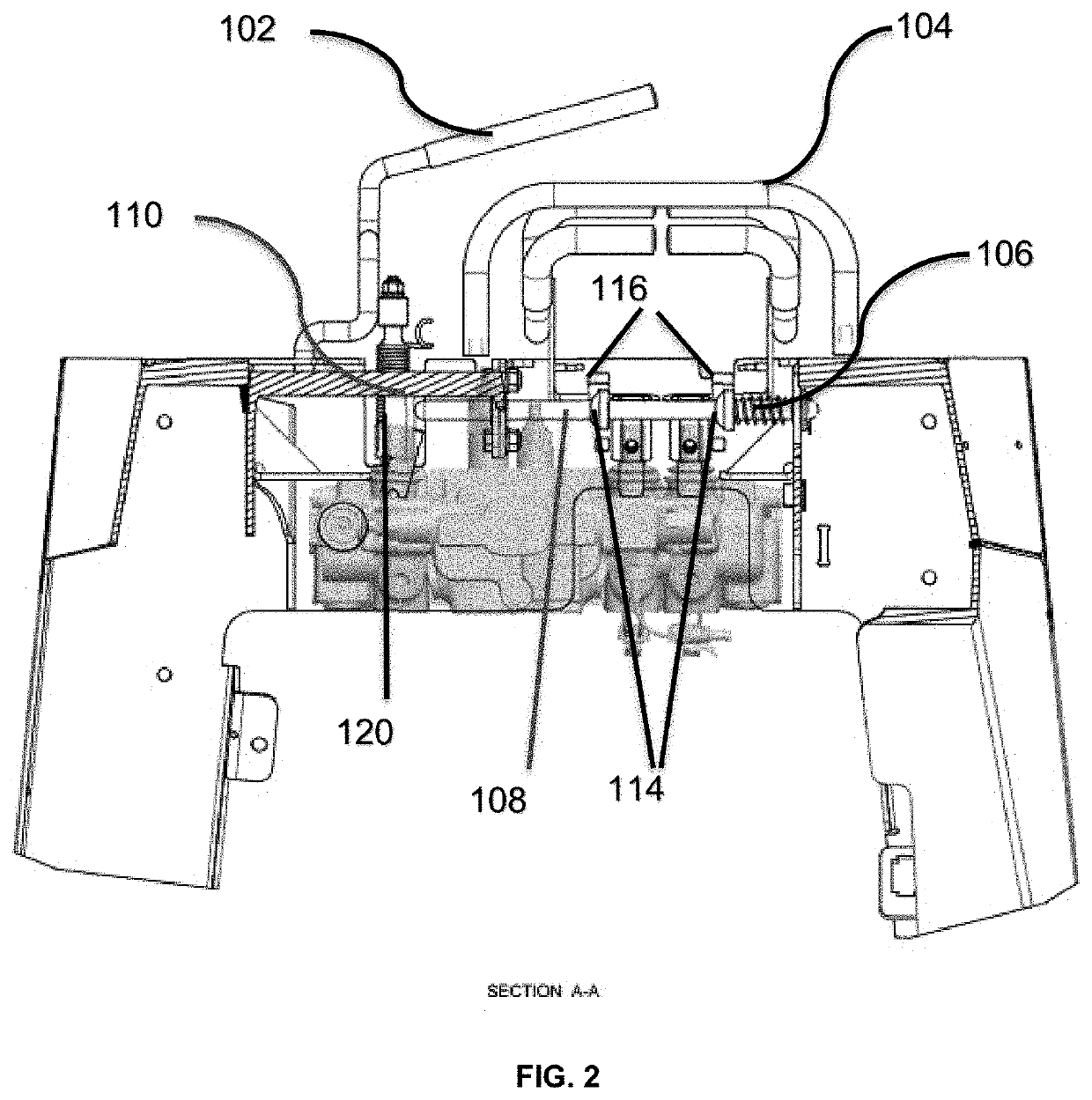
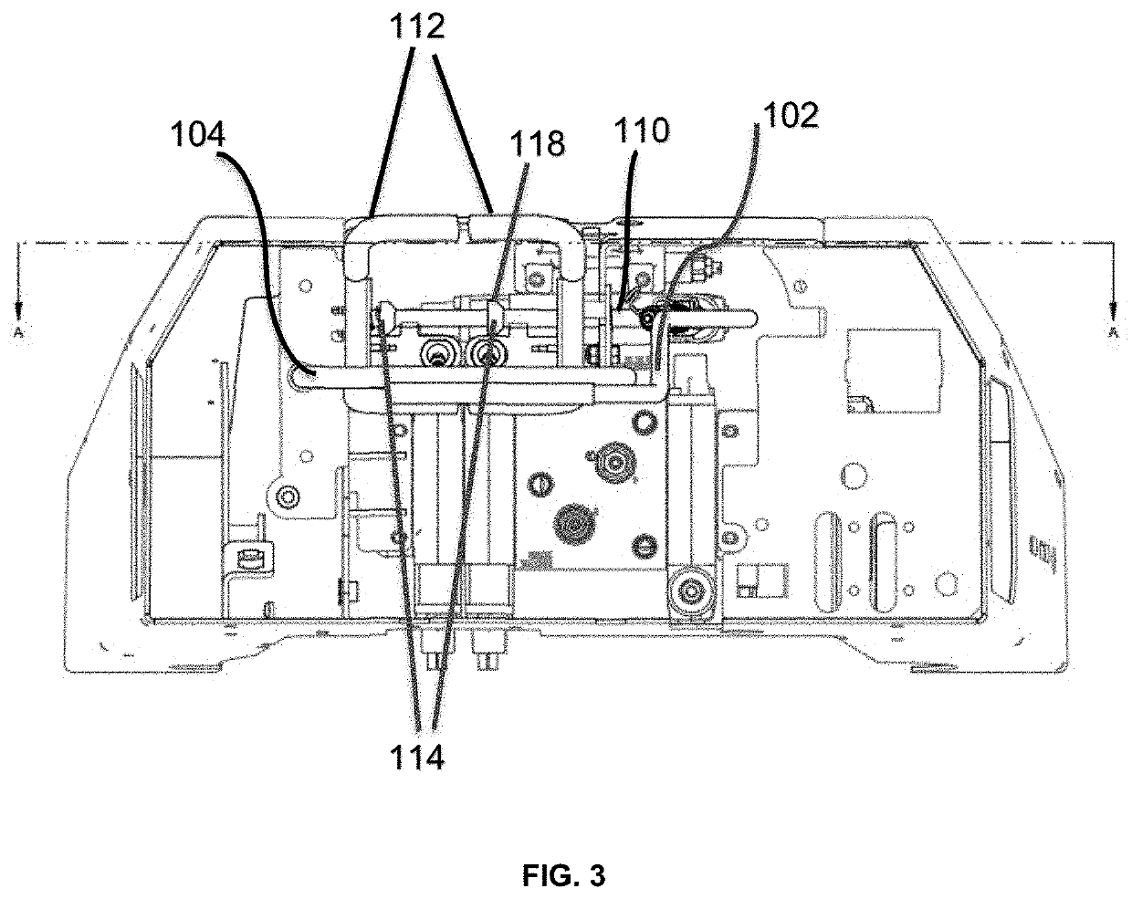
[0024]Specific embodiments of the invention will now be described with reference to the accompanying drawings. This invention may, however, be embodied in many different forms and should not be construed as limited to the embodiments set forth herein; rather, these embodiments are provided so that this disclosure will be thorough and complete, and will fully convey the scope of the invention to those skilled in the art. The terminology used in the detailed description of the embodiments illustrated in the accompanying drawings is not intended to be limiting of the invention. In the drawings.

[0025]The trenching device of the present application operates in two modes, hereinafter, Mode 1 and Mode 2. In Mode 1, trenching blades of the trenching device are lifted up above the ground, the trenching device stops trenching in a reverse direction and functions only as a forward and backward transporting unit. In Mode 2, the trenching blades of the trenching device are lowered to allow initi...


PUM


Abstract

The present Application discloses a trenching device with two operational modes, Mode 1 and mode 2. In Mode 1, the trenching lever is disengaged, the device does not trench, but only functions as a transporting unit in a forward direction with a maximum speed. In Mode 2, the trenching lever is engaged, the device starts trenching, but stops functioning as a transporting unit.

Description

RELATED APPLICATIONS[0001]This application claims benefit of and priority to U.S. Provisional Application Ser. No. 62 / 784,313 filed Dec. 21, 2018 entitled Reverse Tram Interlock, which is hereby incorporated herein by reference in its entirety.FIELD OF THE INVENTION[0002]The present invention pertains to speed acceleration of a walk-behind hydraulic trencher in a forward direction when it functions only as a transporter and not as a trencher.BACKGROUND OF THE INVENTION[0003]A trencher is a chainsaw-like device with blades for digging a trench in the ground to run irrigation lines, cables, etc. The machine is entirely hydraulic. An engine generates hydraulic pressure that is used to run the chain, and also to power the wheels of a vehicle that transports the trencher. In operation, the blade of the trencher is angled from the drive mechanism toward the ground. The blade is dragged along the ground while trenching. This necessarily means that, in the case of smaller trenchers in which...

Claims


Application Information

Patent Timeline
IPC IPC(8): E02F5/14E02F9/22E02F9/20
CPCE02F5/145E02F3/8816E02F9/2253E02F9/2033E02F5/02
Inventor BETZ, II, GERARD G.CUNNINGHAM, RYAN W.KUEMPER, JAMESBENEDICT, MICHAEL H.
Owner TORO CO THE
Why Eureka
Try Eureka