
Wireless climate control system

Inactive Publication Date: 2020-06-25
CARRIER CORP
View PDF0 Cites 2 Cited by
  • Summary
  • Abstract
  • Description
  • Claims
  • Application Information

AI Technical Summary

Benefits of technology

The patent describes a wireless climate control system that includes a wall control, wireless sensors in different climate zones, and a controller that can communicate with both the wall control and the wireless sensors. The controller can convert the climate data received from the wireless sensors to a simulated resistance and communicate it to the wall control. The system can also allow for wireless communication between a mobile device and the controller, as well as between multiple wireless sensors. The technical effects of this system include improved control and efficiency of climate control in multiple zones, as well as improved user experience through wireless communication with the controller.

Problems solved by technology

However, such wall controls cannot communicate to wireless sensors.

Method used


Image

  • Wireless climate control system
  • Wireless climate control system

Examples


Embodiment Construction

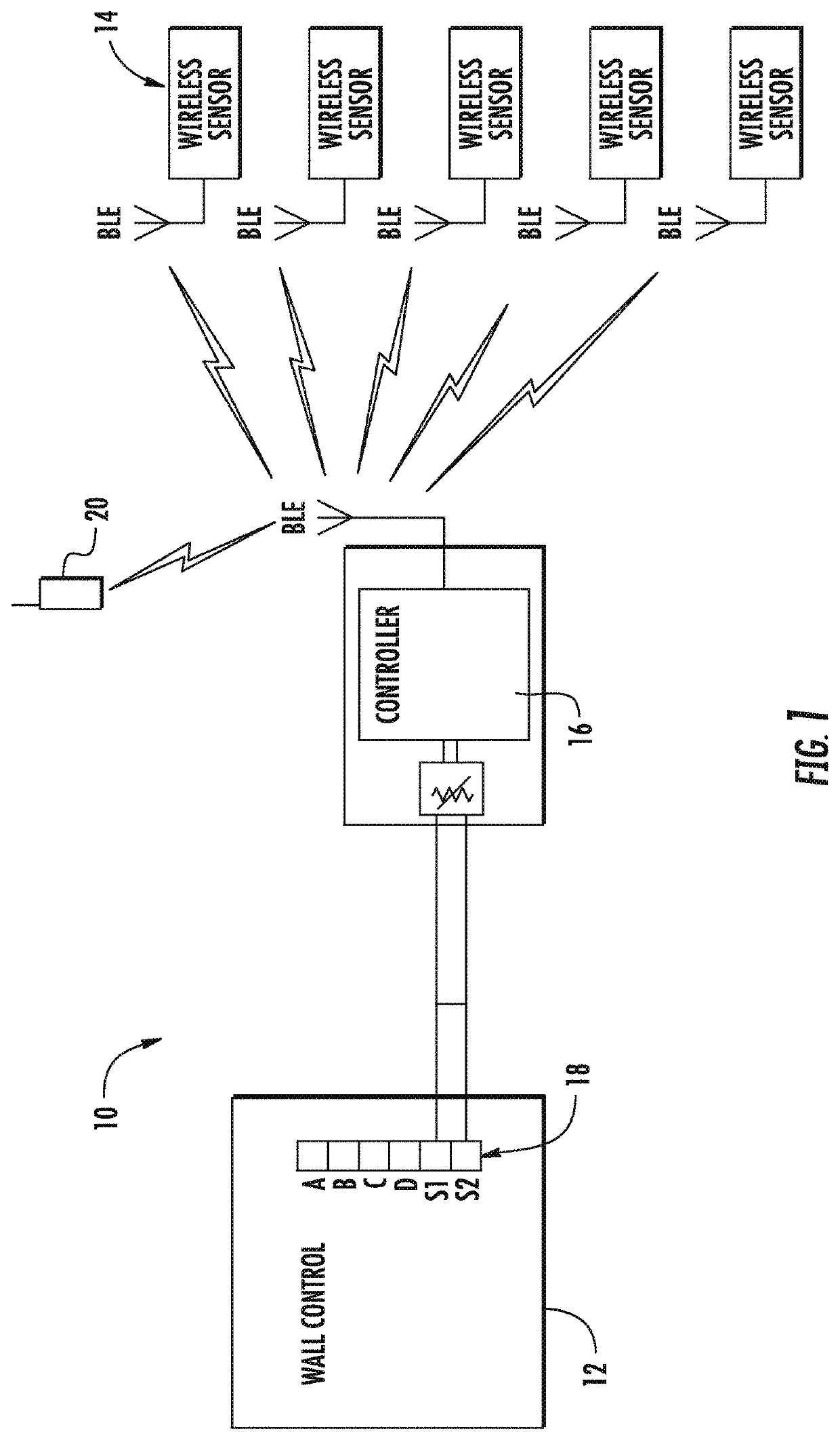
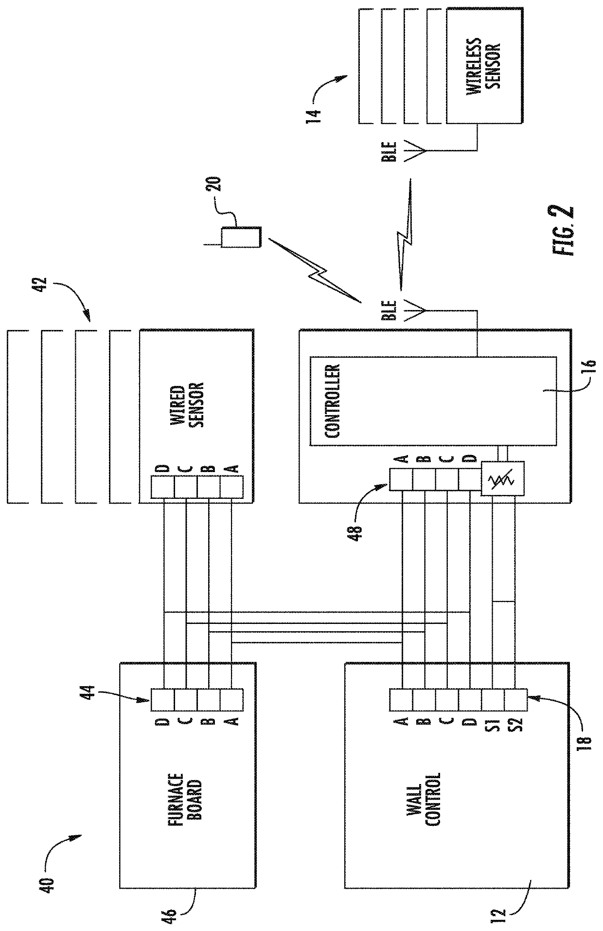
[0022]The Figures show various embodiments of a wireless climate control system that may be employed in a structure that benefits from HVAC technology. For example, the wireless climate control system may be employed in residential or commercial buildings, typically with multiple climate control zones that are to be independently monitored or controlled. The climate control zones may be different rooms and / or floors of a structure.

[0023]FIG. 1 illustrates an embodiment of a wireless climate control system and is generally referenced with numeral 10. The system wireless climate control system 10 includes a wall control 12, which may be referred to as a thermostat. The wall control 12 is accessible to a user as a display for showing various conditions of the wireless climate control system 10, including, for example, temperature, humidity, time, program schedule, etc., related to one or more of the climate control zones. Rather than requiring a hard wired connection with sensor(s) dis...


PUM


Abstract

A wireless climate control system including a wall control having a user interface for controlling a plurality of climate zones. Also disclosed is a wireless sensor disposed in one of the plurality of climate zones. Further disclosed is a controller in operative communication with the wall control and in wireless communication with the wireless sensor.

Description

BACKGROUND[0001]This disclosure relates generally to climate control systems and, more particularly, to a wireless climate control system.[0002]Many wall controls are capable of communicating to multiple wired sensors that measure temperature for zoning purposes. However, such wall controls cannot communicate to wireless sensors.BRIEF SUMMARY[0003]Disclosed is a wireless climate control system including a wall control having a user interface for controlling a plurality of climate zones. Also disclosed is a wireless sensor disposed in one of the plurality of climate zones. Further disclosed is a controller in operative communication with the wall control and in wireless communication with the wireless sensor.[0004]In addition to one or more of the features described above, or as an alternative, further embodiments may include that the wireless communication between the controller and the wireless sensor is made with a Bluetooth Low Energy signal.[0005]In addition to one or more of th...

Claims


Application Information

Patent Timeline
IPC IPC(8): G05D23/19H04L29/08H04W4/70F24F11/56
CPCG05D23/1905H04W4/70H04L67/12F24F11/56
Inventor EICHER, BRIAN W.
Owner CARRIER CORP
Learn More