Oro-Nasal Ventilation Face Mask

Inactive Publication Date: 2020-07-02
RESPITORE LLC
View PDF0 Cites 7 Cited by
  • Summary
  • Abstract
  • Description
  • Claims
  • Application Information

AI Technical Summary

Benefits of technology

[0017]Another advantage of the invention is that creating a pressure differential between the two chambers can improve upper airway patency during events of the patients mouth opening.
[0018]Additional objects, advantages and novel features of the examples will be set forth in part in the description which follows, and in part will become apparent t

Problems solved by technology

Further, this constant and equal pressure provided to the nasal and oral passages simultaneously is inefficient for patients that inhale

Method used


Image

  • Oro-Nasal Ventilation Face Mask
  • Oro-Nasal Ventilation Face Mask
  • Oro-Nasal Ventilation Face Mask

Examples


Embodiment Construction

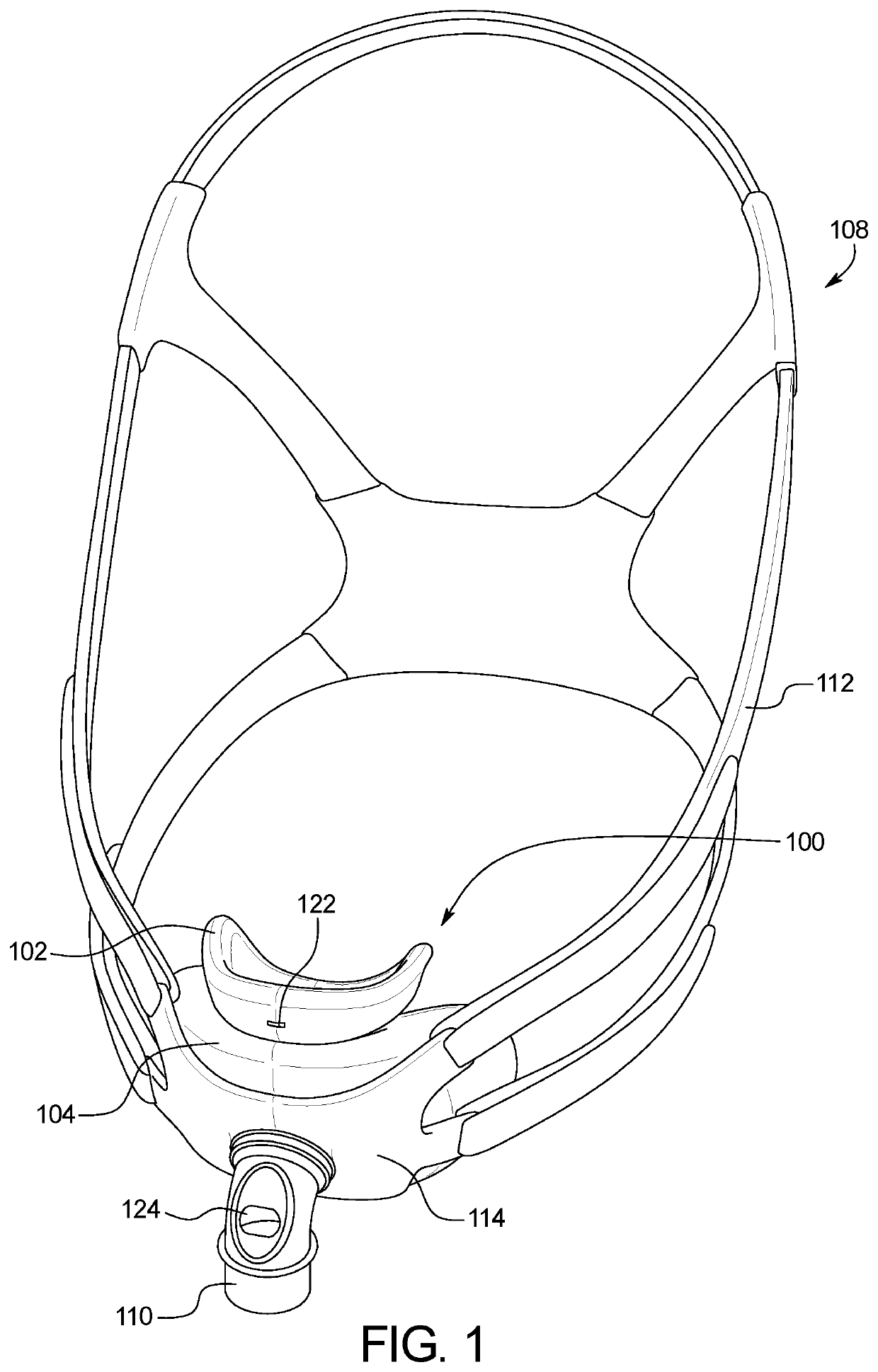
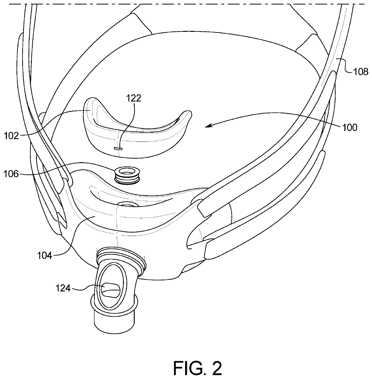
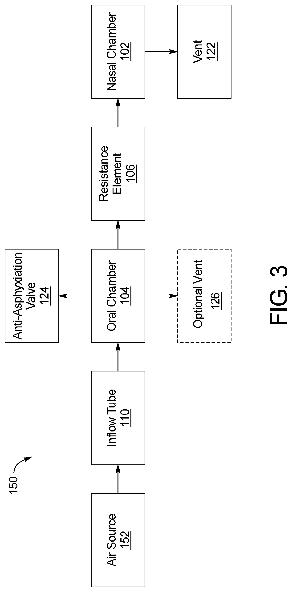
[0032]FIGS. 1-11 illustrate an example of an oro-nasal ventilation face mask 100. As shown in FIG. 1, the oro-nasal ventilation face mask 100 includes a nasal chamber 102 and an oral chamber 104 having a restrictive element 106 positioned therebetween. Each of the nasal chamber 102 and the oral chamber 104 is fully enclosed and sealed against the user's face during use, aside from the connection at the restrictive element. This separation allows for different air pressures to be maintained in the nasal and oral chambers 102, 104 while simultaneously utilizing a single air source. The pressure differential promotes breathing within the patient. In the illustrated embodiment, the face mask 100 is secured to headgear 108 which maintains the positioning of the face mask 100 on the patient during sleep.

[0033]In the embodiment illustrated in FIG. 1, an inflow tube 110 providing air from an air source to the face mask 100 connects to the oral chamber 104. The inflow tube 110 may be of any ...


PUM


Abstract

An oro-nasal ventilation face mask worn by a patient includes a first chamber receiving airflow from an air source, a second chamber in fluid communication with the first chamber, a restrictive element positioned between the first chamber and the second chamber, and a headgear securing the first chamber and the second chamber to the patient. The second chamber includes a vent. Air flows between the first and second chambers through the restrictive element. When the first and second chamber are secured to the patient, the first chamber has a first air pressure, the second chamber has a second air pressure, and the first air pressure is greater than the second air pressure.

Description

CROSS-REFERENCE TO RELATED APPLICATIONS[0001]This application incorporates by reference and claims the benefit of priority to U.S. Provisional Patent Application No. 62 / 785,689 filed Dec. 27, 2019.BACKGROUND OF THE INVENTION[0002]The present subject matter relates generally to face masks. More specifically, the present subject matter relates to face masks for oro-nasal ventilation that include a first chamber and a second chamber, with one or more inter-chamber connections providing a pressure differential between the two chambers.[0003]Many currently available oro-nasal ventilation face masks provide air to the patient equally across both the nasal and oral passages, providing an equilibrium in pressure at the respiratory tract opening. During periods of apnea and at the end of expiration when respiratory flow is zero, air within the oro-nasal cavity remains stagnant even if both the nasal and oral passages are open. Further, this constant and equal pressure provided to the nasal a...

Claims


Application Information

Patent Timeline
IPC IPC(8): A61M16/06
CPCA61M16/0683A61M16/0622A61M16/06A61M2210/0618A61M2210/0625A61M16/0616A61M16/0816A61M16/0866A61M16/208A61M2202/02A61M2205/3331A61M2205/42A61M2206/10A61M2206/11A61M2206/14A61M2202/0085
Inventor BLAXLAND, IAN
Owner RESPITORE LLC
Why Eureka
Try Eureka