Lighting device and display device
a technology of light source and display device, which is applied in the direction of instruments, optical light guides, optics, etc., can solve the problems of difficult brightness improvement and limit in increasing the amount of light emitted by leds, and achieve the effect of precise brightness adjustment and brightness improvemen
- Summary
- Abstract
- Description
- Claims
- Application Information
AI Technical Summary
Benefits of technology
Problems solved by technology
Method used
Image
Examples
first embodiment
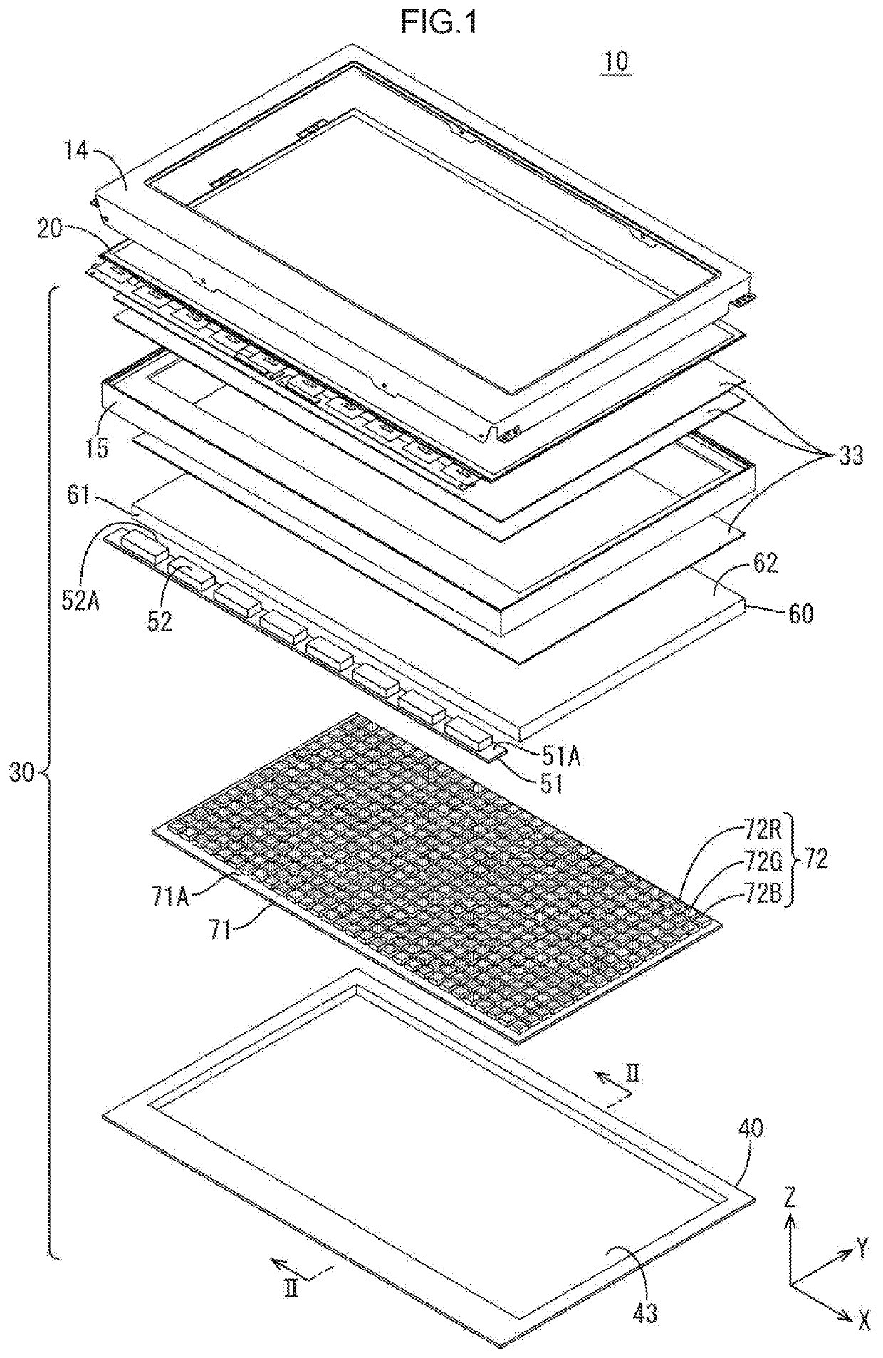
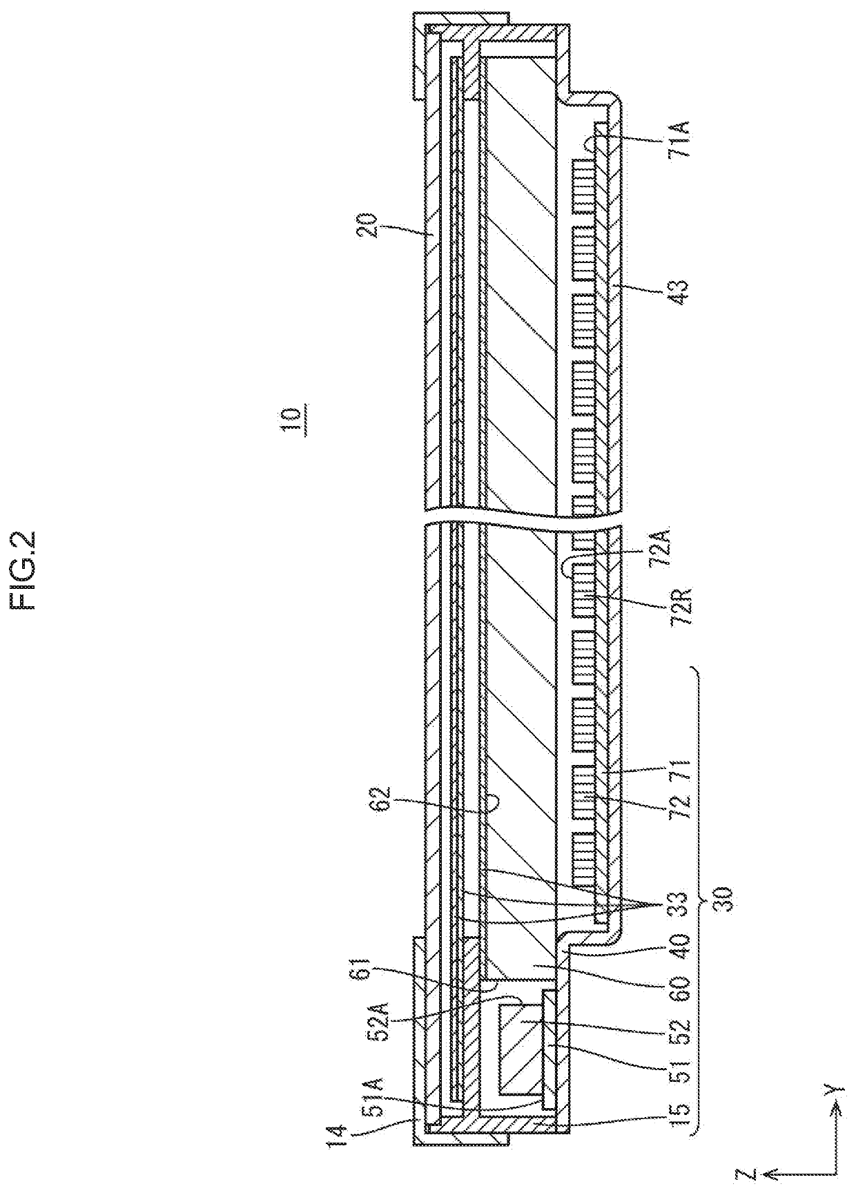
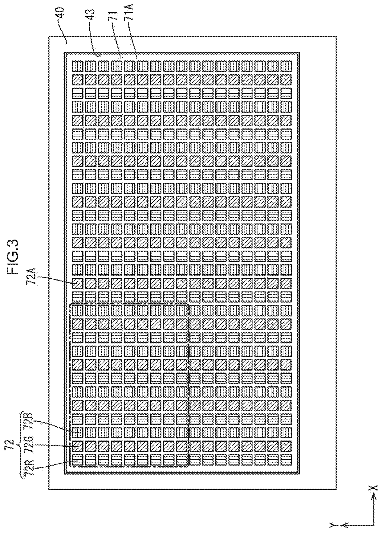
[0021]A first embodiment of the technology described herein will be described in detail with reference to FIGS. 1 to 4. In this section, a liquid crystal display device 10 (an example of a display device) including a backlight unit 30 (an example of a lighting device) will be described. In the drawings, X-axes, Y-axes, and Z-axes may be present. The axes in each drawing correspond to the respective axes in other drawings. In the Z-axis direction, a liquid crystal panel 20 side relative to the backlight unit 30 is defined as a front side and an opposite side from the liquid crystal panel 20 side is defined as a rear side.
[0022]As illustrated in an exploded perspective view in FIG. 1, the liquid crystal display device 10 includes the liquid crystal panel 20 (an example of a display panel) and the backlight unit 30 (an example of a lighting device). The liquid crystal panel 20 is configured to display images. The backlight unit 30 is configured to illuminate the liquid crystal panel 20...
second embodiment
[0040]A second embodiment of the technology described herein will be described with reference to FIG. 9. In the second embodiment, the LEDs 52, which are included in the first light sources, arc disposed opposite either side surface of the light guide plate 60. Components, functions, and effects similar to those of the first embodiment previously described will not be described.
[0041]As illustrated in FIG. 9, the LEDs 52 are disposed opposite the first side surface 61 of the light guide plate 60 and the second side surface 63 of the light guide plate 60 on an opposite side from the first side surface 61. The light emitted by the LEDs 52 enters the light guide plate 60 through the side surfaces 61 and 63 of the light guide plate 60. According to the configuration, the brightness further improves. This configuration is preferable for achieving uniform brightness distribution.
third embodiment
[0042]A third embodiment, of the technology described herein will be described with reference to FIG. 10. The third embodiment includes a cold cathode fluorescent lamp (CCFL) 152 provides as a first light source. Components, functions, and effects similar to those of the first embodiment previously described will not foe described.
[0043]As illustrated in FIG. 10, the cold cathode fluorescent lamp 152 is disposed opposite the first side surface 61 of the light guide plate 60 in this embodiment. The cold cathode fluorescent lump 152 is supported by the chassis 40 with clips. The cold cathode fluorescent lamp 152 has a diameter about equal to a height of the first side surface in the Z-axis direction (about 1 mm to 3 mm in this embodiment). The cold cathode fluorescent lamp 152 has a length about equal to the length of the first side surface in the X-axis direction. The cold cathode fluorescent lamp 152 is less expensive in comparison to the LEDs 52. With the cold cathode fluorescent l...
PUM
| Property | Measurement | Unit |
|---|---|---|
| area | aaaaa | aaaaa |
| area | aaaaa | aaaaa |
| depth | aaaaa | aaaaa |
Abstract
Description
Claims
Application Information
 - R&D
- Intellectual Property
- Life Sciences
- Materials
- Tech Scout
- Unparalleled Data Quality
- Higher Quality Content
- 60% Fewer Hallucinations
Browse by: Latest US Patents, China's latest patents, Technical Efficacy Thesaurus, Application Domain, Technology Topic, Popular Technical Reports.
© 2025 PatSnap. All rights reserved.Legal|Privacy policy|Modern Slavery Act Transparency Statement|Sitemap|About US| Contact US: help@patsnap.com


