LED dimming control method and dimming driving device

A technology of LED driving and dimming driving, which is applied in the direction of electrical components to achieve precise brightness adjustment, reduce voltage and current impact, and avoid the working state of repeated switching.

Active Publication Date: 2022-04-08
X-SIGNAL INTEGRATED CO
View PDF10 Cites 1 Cited by
  • Summary
  • Abstract
  • Description
  • Claims
  • Application Information

AI Technical Summary

Problems solved by technology

The present invention aims at the problem that the current LED backlight modulation has only one non-zero stable point, and proposes a method that utilizes a DAC (digital-to-analog converter) to output multi-stable point control signals to modulate the LED backlight

Method used


Image

  • LED dimming control method and dimming driving device
  • LED dimming control method and dimming driving device
  • LED dimming control method and dimming driving device

Examples


Embodiment 1

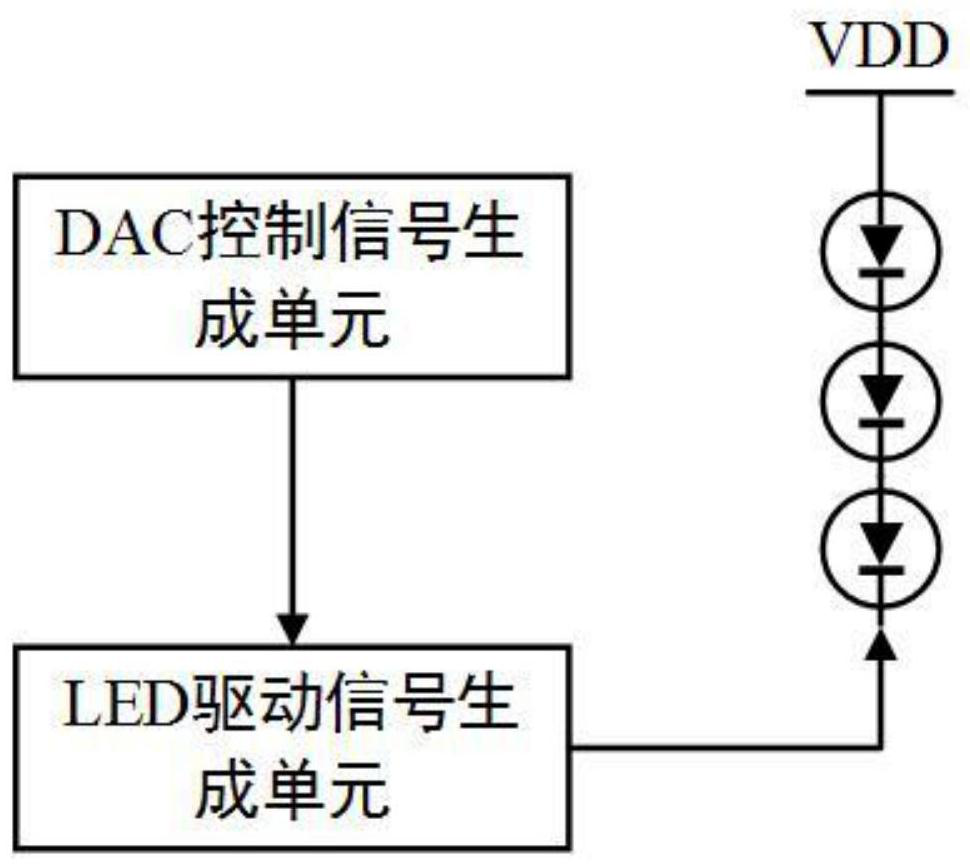
[0036] Such as image 3 As shown, the LED dimming driving device in this embodiment includes a DAC control signal generating unit and an LED driving signal generating unit.

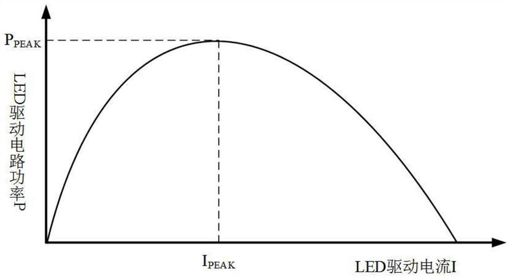
[0037] Such as Figure 4 As shown, the DAC control signal generating unit generates a first control signal and a second control signal, and the first control signal is input to the LED driving signal generating unit to generate a first driving current I 1 , the second control signal is input to the LED drive signal generation unit to generate a second drive current I 2 , the first drive current I 1Less than the maximum power current value I corresponding to the peak power of the LED drive signal generating unit peak , the second drive current I 2 Greater than the corresponding maximum power current value I under the peak power of the LED drive signal generating unit peak . The first drive current I 1 and the second driving current I 2 That is, the driving current flowing through the LED light-emit...

Embodiment 2

[0045] This embodiment is a further improvement on Embodiment 1 above, and the LED dimming driving device in this embodiment includes a DAC control signal generating unit and an LED driving signal generating unit.

[0046] Such as Figure 5 As shown, the DAC control signal generating unit generates a first control signal, a second control signal and a third control signal, and the first control signal is input to the LED driving signal generating unit to generate a first driving current I 1 , the second control signal is input to the LED drive signal generation unit to generate a second drive current I 2 , the third control signal is input to the LED drive signal generation unit to generate a third drive current I 3 ,

[0047] The first drive current I 1 Less than the corresponding maximum power current value I under the peak power of the LED drive signal generating unit peak , the second drive current I 2 and the third driving current I 3 Greater than the corresponding ...

Embodiment 3

[0055] This embodiment is a further improvement on Embodiment 1 above, and the LED dimming driving device in this embodiment includes a DAC control signal generating unit and an LED driving signal generating unit.

[0056] Such as Figure 6 As shown, the DAC control signal generating unit generates a first control signal and a second control signal, and the first control signal is input to the LED driving signal generating unit to generate a first driving current I 1 , the second control signal is input to the LED drive signal generation unit to generate a second drive current I 2 , the first drive current I 1 Less than the maximum power current value I corresponding to the peak power of the LED drive signal generating unit peak , the second drive current I 2 Greater than the corresponding maximum power current value I under the peak power of the LED drive signal generating unit peak . The first drive current I 1 and the second driving current I 2 That is, the driving c...


PUM


Abstract

The invention discloses an LED dimming driving device. The LED dimming driving device comprises a DAC control signal generation unit and an LED driving signal generation unit. The DAC control signal generation unit generates a first control signal and a second control signal, the first control signal is input to the LED drive signal generation unit to generate a first drive current I1, and the second control signal is input to the LED drive signal generation unit to generate a second drive current I2. The first driving current I1 is smaller than the corresponding maximum power current value Ipeak under the LED peak power, and the second driving current I2 is larger than the corresponding maximum power current value Ipeak under the LED peak power; the time length of a clock period of a control signal generated by the DAC control signal generation unit is T, the duration of a first control signal is T1 and the duration of a second control signal is T2 in every clock period, and T1 + T2 = T; the brightness of the LED light-emitting component can be adjusted by adjusting the duration T1 of the first control signal and the duration T2 of the second control signal.

Description

technical field [0001] The present invention relates to the technical field of LED dimming driving, in particular to an LED dimming control method and a dimming driving device. Background technique [0002] LED backlight has the advantages of long life, low power consumption, and environmental protection, and is widely used in backlight applications. With more and more applications, the design of its drive circuit becomes more important. PWM (Pulse Width Modulation) dimming is currently the most A mainstream dimming technology used in LED dimming products. In the analog signal circuit, the digital output controls the brightness change of the LED. This modulation method has many advantages compared with the traditional analog signal dimming, but At the same time, there are certain shortcomings, that is, there is only one non-zero stable point in PWM, which will cause the following problems in the process of modulating the LED current: (1) The difference between rising and fal...

Claims


Application Information

Patent Timeline
Patent Type & Authority Applications(China)
IPC IPC(8): H05B45/10H05B45/50
CPCH05B45/10H05B45/50
Inventor 阳冠欧孔令新
Owner X-SIGNAL INTEGRATED CO
Why Eureka
Try Eureka