
Liquid ejecting device and a method for correcting landing position deviation of liquid

a liquid ejecting device and liquid technology, applied in the direction of power drive mechanisms, spacing mechanisms, printing, etc., can solve the problems of insufficient consideration for correcting the landing position deviation, and the deviation of the landing position of ink

Active Publication Date: 2020-07-23
SEIKO EPSON CORP
View PDF0 Cites 5 Cited by
  • Summary
  • Abstract
  • Description
  • Claims
  • Application Information

AI Technical Summary

Benefits of technology

The present disclosure provides a liquid ejecting device that can eject liquid onto a medium. The device includes a supporting unit to hold the medium, an ejecting unit to spray liquid onto the medium, a scanning driving unit to move the ejecting unit in a direction, and a control unit to manage the ejecting unit and the scanning driving unit. The control unit can perform processes such as ejecting liquid to form a velocity test pattern, calculating the velocity of the liquid based on the test pattern, and setting a correction value to adjust the timing of the liquid spray. The technical effect of the present invention is to provide a device that can accurately control the timing of liquid ejection onto a medium and to continuously adjust the timing as the ejecting unit moves.

Problems solved by technology

In this printing apparatus, there is a possibility that landing position deviation of ink may occur in a forward path and a backward path during the bi-directional printing.
However, in the past, there has been a problem in that sufficient consideration has not been made to correct the landing position deviation due to the error in the ink ejection velocity.
This problem is not limited to printing apparatuses, and is a common problem with other types of liquid ejecting devices that eject liquid other than ink from ejecting units.

Method used


Image

  • Liquid ejecting device and a method for correcting landing position deviation of liquid
  • Liquid ejecting device and a method for correcting landing position deviation of liquid
  • Liquid ejecting device and a method for correcting landing position deviation of liquid

Examples


Embodiment Construction

[0015]A. Configuration of Apparatus:

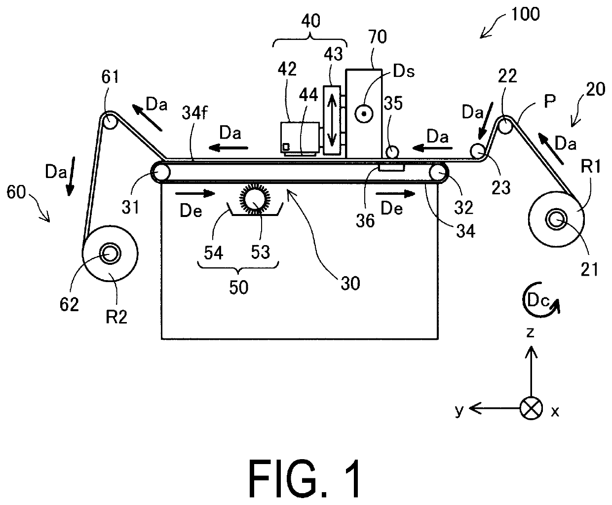
[0016]FIG. 1 is a right side view of a printing apparatus 100 as an exemplary embodiment of a liquid ejecting device. In other words, a left side of a paper surface of FIG. 1 corresponds to a front side of the printing apparatus 100, and a right side of the paper surface corresponds to a rear side. An x-axis direction is a direction from a right side surface toward a left side surface of the printing apparatus 100, a y-axis direction is a direction from a back side toward a front side of the printing apparatus 100, and a z-axis direction is a direction vertically upward. The x-, y-, z-axis directions are orthogonal to each other. X-, y-, z-axis directions in other views also illustrate identical directions to those in FIG. 1.

[0017]The printing apparatus 100 includes a feeding portion 20, a transport unit 30, a carriage 40, a cleaning unit 50, a winding unit 60, and a scanning driving unit 70.

[0018]The feeding portion 20 is a mechanism for feeding ...


PUM


Abstract

A liquid ejecting device includes a supporting unit supporting a medium, an ejecting unit ejecting liquid onto the medium, a scanning driving unit moving the ejecting unit, and a control unit controlling the ejecting unit and the scanning driving unit. The control unit is configured to be capable of performing, a first processing for forming a test pattern, and acquiring an ejection velocity parameter associated with an ejection velocity of the liquid detected from the test pattern, a second processing for calculating the ejection velocity of the liquid from the ejection velocity parameter, calculating a first correction component that depends on the calculated ejection velocity, and setting a correction value including the first correction component, and a third processing for correcting ejection timing of the liquid using the correction value, when the liquid is ejected from the ejecting unit onto the medium as the ejecting unit is moved.

Description

[0001]The present application is based on, and claims priority from JP Application Serial Number 2019-005789, filed Jan. 17, 2019, the disclosure of which is hereby incorporated by reference herein in its entirety.BACKGROUND1. Technical Field[0002]The present disclosure relates to a liquid ejecting device for ejecting liquid onto a medium, and particularly relates to a technique for correcting landing position deviation of liquid.2. Related Art[0003]JP-A-2009-286141 discloses a printing apparatus capable of performing bi-directional printing in which printing is performed by reciprocating a carriage having a printing head mounted thereon. In this printing apparatus, there is a possibility that landing position deviation of ink may occur in a forward path and a backward path during the bi-directional printing. Thus, in the related art, landing position deviation during bi-directional printing is corrected by printing a correction pattern by the bi-directional printing, detecting the ...

Claims


Application Information

Patent Timeline
Patent Type & Authority Applications(United States)
IPC IPC(8): B41J2/045B41J25/308
CPCB41J25/308B41J2/04508B41J2/04586B41J2029/3935B41J19/145B41J25/3082B41J2/04573B41J2/04505B41J2/04506
Inventor KOBAYASHI, TOSHIYUKI
Owner SEIKO EPSON CORP
Learn More