Pump With Segmented Fluid End Housing and In-Line Suction Valve

a technology of fluid end housing and in-line suction valve, which is applied in the direction of pump components, positive displacement liquid engines, liquid fuel engine components, etc., can solve the problems of fluid end structural failure, high stress in the sharp cornered thread roots, and cyclic fatigu

Inactive Publication Date: 2020-07-23
ALTIS INVESTMENTS LLC
View PDF0 Cites 24 Cited by
  • Summary
  • Abstract
  • Description
  • Claims
  • Application Information

AI Technical Summary

Benefits of technology

The present invention is a modular design for a fluid end assembly used in high-pressure pumps. The design has several advantages. First, maintenance is easier because individual modules can be easily removed and replaced. Second, the design allows for easy replacement of a packing box module if it fails, instead of replacing the entire fluid end assembly. Third, the design reduces stress and the weight of the assembly, which is critical in truck-mounted pumps. The central fluid module has multiple fluid chambers with plunger bores and discharge bores, and a discharge port is required to contain high pump pressure. The discharge port is designed to reduce flow rate and prevent structural failure. The invention also includes a suction valve spring retainer / plunger spacer with a sacrificial port to absorb erosion damage and prevent premature failure of the central fluid module.

Problems solved by technology

The threads in the fluid end housing necessary to accommodate the threaded bolts resulted in high stresses in the sharp cornered thread roots.
These high stresses combined with stresses at the intersection of the discharge and suction valve bores with the plunger bore resulted in cyclic fatigue and structural failure of the fluid end.
In addition to structural failure due to high stress, packing box failures due to erosion from the failure of the packing seal are a common problem; replacing the packing box module is for significantly less costly than replacing the entire fluid end assembly.

Method used


Image

  • Pump With Segmented Fluid End Housing and In-Line Suction Valve
  • Pump With Segmented Fluid End Housing and In-Line Suction Valve
  • Pump With Segmented Fluid End Housing and In-Line Suction Valve

Examples


Embodiment Construction

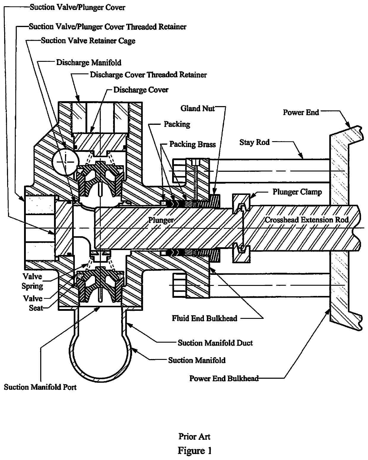
[0055]FIG. 8 schematically illustrates a cross-section of an embodiment of the fluid end assembly 100 of the present invention showing its connection to a power end by multiple stay rods 6. As opposed to the fluid end housing of the prior art as illustrated in FIG. 1, fluid end assembly 100 of the present invention is configured with the suction manifold 5 mounted in a position on the fluid end housing opposite the power end of the pump. The primary component of the fluid end assembly 100 of the present invention is modular housing 101 which is connected to the power end by multiple stayrods 6 and stayrod retaining nuts 7.

[0056]FIG. 9 and FIG. 10A schematically illustrates an orthogonal and top view respectively of the exterior of the fluid end assembly 100. Fluid end assembly 100 comprises modular housing 101, suction manifold 5, and various internal components. The modular housing 101 includes one central fluid module 2 and multiple packing box modules 3, suction seat modules 1, s...


PUM


Abstract

A plunger pump fluid end in which the suction valve and seat is aligned with the plunger and the fluid end housing is constructed with multiple modules. Modules are held in a rigid assembly by staybolts that connect to the power end of the plunger pump. Said staybolts pass though bores in the central fluid module and the suction seat module and bound by a conventional threaded nut. Packing box modules are bound to the central fluid module by bolts that also pass through separate bores in the same central module. A suction valve spring retainer / plunger spacer within the plunger bore of the assembly shields the intersection of the plunger bore and the discharge bore from destructive erosion damage.

Description

PRIORITY DATA[0001]This patent application is a Divisional of, and claims priority to, U.S. Non-Provisional patent application Ser. No. 15 / 732,441, filed on Nov. 13, 2017. This patent application further claims priority to U.S. Non-Provisional patent application Ser. No. 15 / 330,213, filed on Aug. 23, 2016, and also claims priority to U.S. Non-Provisional patent application Ser. No. 15 / 330,212, filed on Aug. 23, 2016. Each of the aforementioned patent applications, by this reference, are incorporated herein for all purposes.FIELD OF THE INVENTION[0002]The invention relates generally to high-pressure plunger pumps used, for example, in oil field operations. More particularly, the invention relates to a modular fluid end design with an internal bore configuration that improves flow, improves fluid end filling, and incorporates structural features for stress-relief in high-pressure plunger pumps.BACKGROUND[0003]Engineers typically design high-pressure oil field plunger pumps in two sect...

Claims


Application Information

Patent Timeline
Patent Type & Authority Applications(United States)
IPC IPC(8): F04B53/10F04B53/16F04B1/122F04B1/0456F04B1/145F04B1/143F04B1/0461F04B1/053F04B1/0538F04B53/02F04B1/0448
CPCF04B53/1087F04B1/0461F04B1/143F04B1/053F04B53/02F04B1/145F04B1/122F04B53/164F04B1/0448F04B1/0538F04B1/16F04B53/16F04B1/0456
Inventor BLUME, GEORGE H.
Owner ALTIS INVESTMENTS LLC
Why Eureka
Try Eureka