Method of manufacturing a magnetic head using a magneto-resistive effect

a technology of magnetoresistive effect and manufacturing method, which is applied in the field of magnetic head using magnetoresistive effect, can solve the problems of insufficient reduction of the width of the magneto-resistive effect element, insufficient concentration of external magnetic field, and insufficient improvement of the efficiency of the magneto-resistive effect, so as to improve the effect of canceling the magnetic domain of other portions of the free layer, improve the barkhausen noise, and simplify manufacturing

Inactive Publication Date: 2007-07-17
SONY CORP
View PDF12 Cites 13 Cited by
  • Summary
  • Abstract
  • Description
  • Claims
  • Application Information

AI Technical Summary

Benefits of technology

[0027]In the magnetic head including the magnetic sensing portion formed of the above-mentioned magneto-resistive effect element having the SVMR configuration or the TMR configuration according to the present invention, since opposing side surfaces are formed as one plane or one continuous curved surface and are substantially the same in width in at least the free layer into which the external magnetic field is introduced and the nearby portions, i.e., the nonmagnetic conductive layer serving as substantially the operation portion which can achieve the magneto-resistive effect or the tunnel barrier layer and the fixed layer, the width of this portion can be reduced necessarily and sufficiently and the sense current can be concentrated so that the magneto-resistive effect can be increased. Therefore, the magnetic head in which a detection output of a signal magnetic field from a magnetic recording medium can be increased can be comprised of the magneto-resistive effect element which can detect the external magnetic field with high sensitivity.
[0028]Further, as described above, in the magneto-resistive effect element and the magnetic head, when the positional relationship between the hard magnetic layer and the free layer is selected in such a manner that the central portion of both of the hard magnetic layer and the free layer in the film thickness directions may substantially agree with each other, the magnetic field from the hard magnetic layer can be effectively applied to the free layer and the stability of the free layer can be improved more.
[0032]On the other hand, when the positional relationship between the hard magnetic layer and the free layer is selected in such a manner that the central portions of both of the hard magnetic layer and the free layer in the film thickness directions substantially agree with each other, i.e., the planes in which both of the hard magnetic layer and the free layer are disposed are not flush with each other, the magnetic field from the hard magnetic layer can be applied to the free layer effectively and effects for canceling magnetic domains of other portions of the free layer can be improved more. Thus, the stability of the free layer, accordingly, the improvement of the Barkhausen noise can be increased.
[0033]Furthermore, according to the above-mentioned manufacturing method of the present invention, since this substantial operation portion can be formed by a series of patterning with the same pattern, i.e., the same mask, the manufacturing can be simplified.

Problems solved by technology

Further, in the case of the CIP configuration, since upper and lower portions are sandwiched by insulating materials, heat radiation property is poor and hence there arises a problem of a reliability such as a risk in which the films will be fused when the magneto-resistive effect element or the magnetic head using magneto-resistive effect is being continuously used during a long period of time.
However, as described above, when the width of the free layer is made large, since the width of the free layer is increased, the width of the magneto-resistive effect element cannot be reduced sufficiently and the external magnetic field cannot be concentrated sufficiently.
Then, there arises a problem in which an efficiency of a magneto-resistive effect cannot be improved sufficiently.

Method used


Image

  • Method of manufacturing a magnetic head using a magneto-resistive effect
  • Method of manufacturing a magnetic head using a magneto-resistive effect
  • Method of manufacturing a magnetic head using a magneto-resistive effect

Examples


first embodiment

[0101]An embodiment will be described with reference to FIGS. 1 to 17 in conjunction with a manufacturing method according to an embodiment of the present invention.

[0102]In this embodiment, there are constructed a GMR element having an SVMR configuration and a magnetic head having this element.

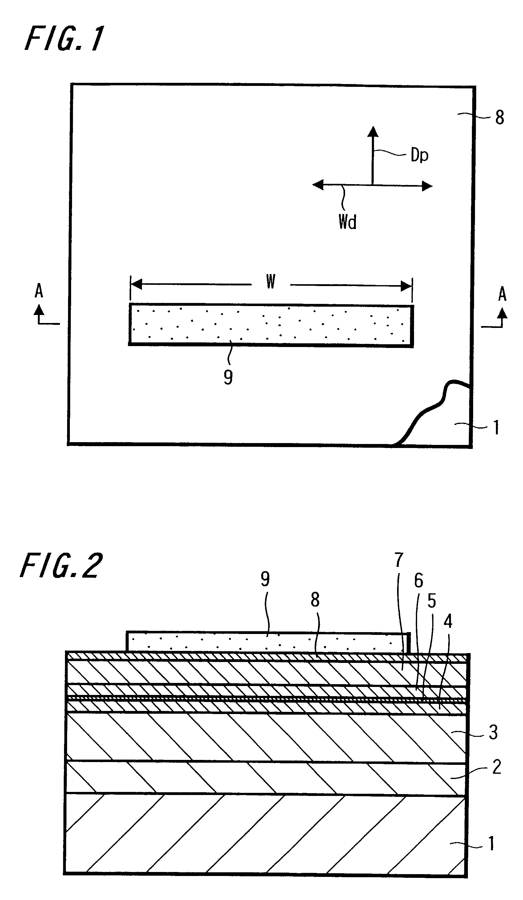
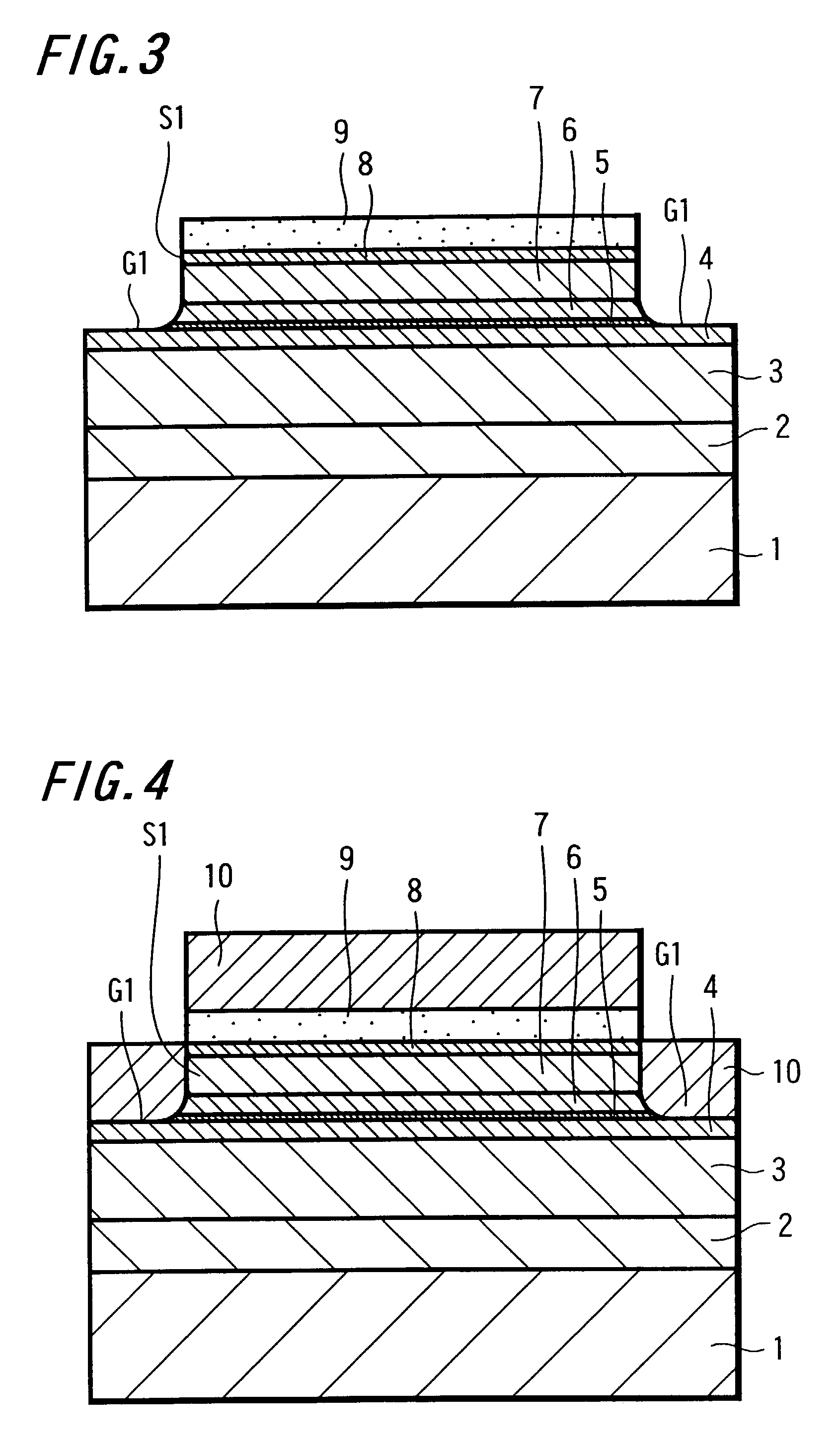
[0103]As FIG. 1 shows a schematic plan view and FIG. 2 shows a schematic cross-sectional view taken along the line A-A, there is prepared a substrate 1 made of AlTiC (AlTiC) having a thickness of 2 mm, for example, on which there is deposited a first shield and electrode layer 2 made of NiFe having a thickness of 2 μm serving as one magnetic shield layer of a finally obtained magnetic head and which constructs one electrode by plating.

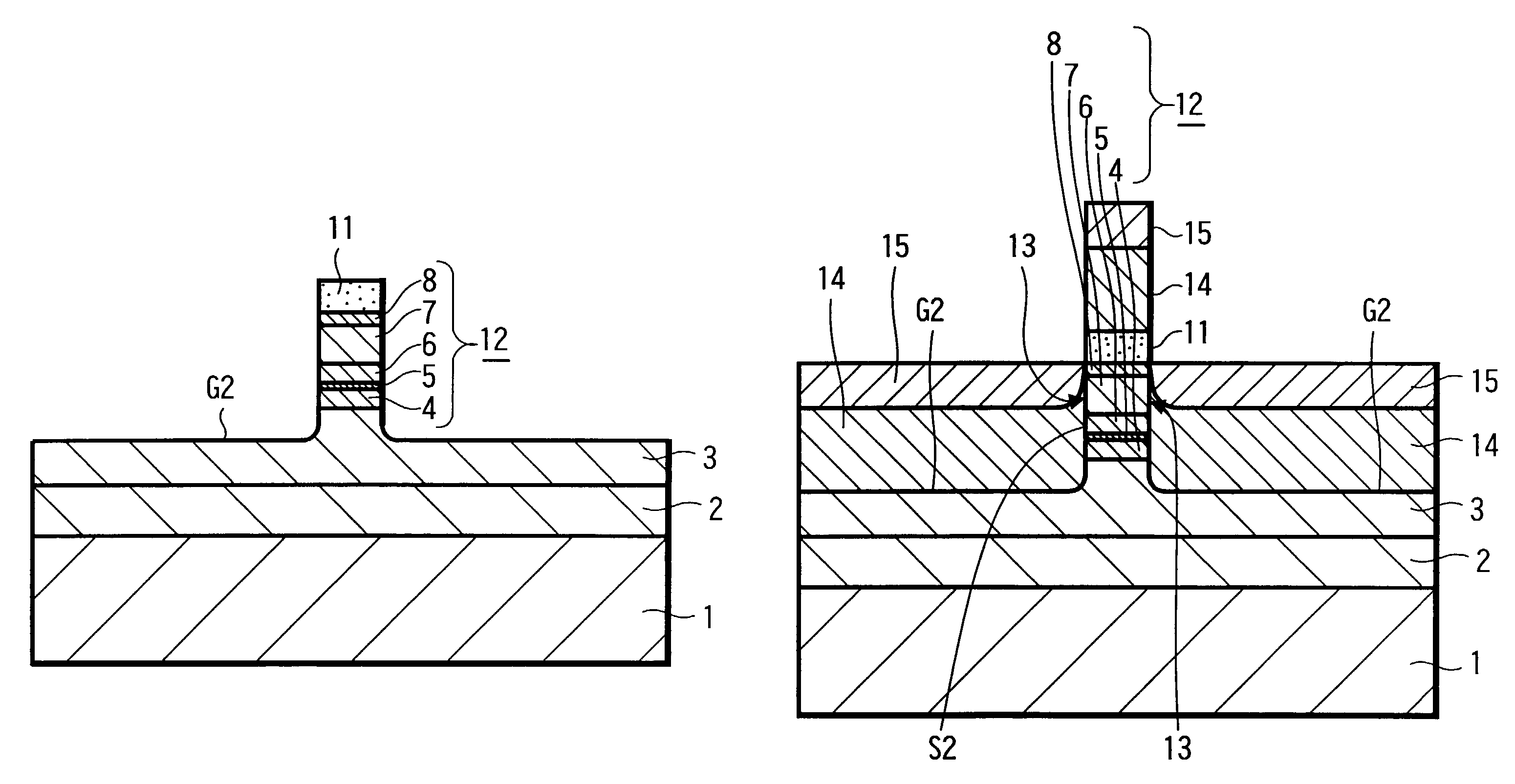
[0104]Then, on the first shield and electrode layer 2, there are deposited and laminated a nonmagnetic layer 3 comprising a lower gap layer, a free layer and magnetic flux introducing layer 4 serving as a free layer in the SVMR configuration and which comprises ...

second embodiment

[0152]An embodiment of this case will be described with reference to FIGS. 22 to 38 in conjunction with an example of a manufacturing method according to the present invention.

[0153]First, as FIG. 22 shows a schematic plan view and FIG. 23 shows a schematic cross-sectional view taken along the line A-A in FIG. 22, also in this case, there is prepared a substrate 1 made of AlTiC (AlTiC) having a thickness of 2 mm, for example, on which there is formed a first shield and electrode layer 2 serving as one magnetic shield layer of a finally obtained magnetic head and which comprises one electrode by plating.

[0154]Then, on this first shield and electrode layer 2, there are laminated and deposited an underlayer 41, an antiferromagnetic layer 7, a fixed layer 6, a nonmagnetic conductive layer of a spacer layer 5 and a free layer 40, each having a conductivity, in that order, by sputtering.

[0155]The first shield and electrode layer 2 can be comprised of NiFe having a thickness of 2 μm.

[0156]...

third embodiment

[0196]An example of this case will be described with reference to FIGS. 41 to 63.

[0197]Also in this case, as FIG. 41 shows a schematic plan view and FIG. 42 shows a schematic cross-sectional view taken along the line A-A in FIG. 41, there is prepared a substrate 1 made of AlTiC (AlTiC) having a thickness of 2 nm on which there is deposited a first shield and electrode layer 2 made of NiFe having a thickness of 2 μm, for example, serving as one magnetic shield layer of a finally obtained magnetic head and which comprises one electrode by plating, for example.

[0198]Then, an underlayer 41, an antiferromagnetic layer 7A, a fixed layer 6, a spacer layer 5A, i.e., nonmagnetic conductive layer, a common free layer 40, each having conductivity, comprising one SVMR element and a spacer 5B, i.e., nonmagnetic conductive layer, a fixed layer 6B, an antiferromagnetic layer 7B, a protective layer 8, i.e., capping layer comprising the other SVMR element are sequentially laminated and deposited on ...


PUM

PropertyMeasurementUnit
thicknessaaaaaaaaaa
thicknessaaaaaaaaaa
thicknessaaaaaaaaaa

Abstract

A method of manufacturing a magnetic head including a magnetic sensing portion formed of a magnetoresistive effect element, a magnetoresistive effect magnetic head manufacturing method depositing, via a film deposition process, a lamination layer having a free layer comprised of a soft magnetic material of which the magnetization is rotated in response to an external magnetic field, a fixed layer comprised of a ferromagnetic material, an antiferromagnetic layer for fixing the magnetization of said fixed layer, a magnetic flux introducing layer with a tip end of which is opposed to a surface which is brought in contact with or opposed to a magnetic recording medium, and a spacer layer interposed between said free layer and said fixed layer; patterning at least said free layer and said fixed layer with a mask such that opposing side surfaces of said free layer and said fixed layer are formed of one continuous surface; and forming hard magnetic layers having high or low resistance for maintaining a magnetic stability of said free layer in contact with said opposing side surfaces.

Description

RELATED APPLICATION DATA[0001]This application is a continuation-in-part of International Patent Application. No. PCT / JP01 / 09734, filed Nov. 7, 2001. The present and foregoing applications claim priority to Japanese Patent Application No. P2000-340636, filed Nov. 8, 2000. All of the foregoing applications are incorporated herein for all purposes by reference to the extent permitted by law.TECHNICAL FIELD[0002]The present invention relates to a magneto-resistive effect element (MR element) for detecting an external magnetic field and particularly relates to a magnetic head using magneto-resistive effect, that is, a magnetic head using magneto-resistive effect including a GMR (Giant Magneto-resistive) element having a spin-valve type magneto-resistive effect element (SVMR) configuration or an MR element having a tunnel type MR (TMR) configuration having a tunnel barrier film as a magnetic sensing portion and a manufacturing method thereof.BACKGROUND OF THE INVENTION[0003]A spin-valve ...

Claims


Application Information

Patent Timeline
Patent Type & Authority Patents(United States)
IPC IPC(8): G11B5/187G01R33/09G11B5/31G11B5/39H01F10/08H01F10/32H01F41/18H01L43/08H01L43/12
CPCB82Y10/00G01R33/093G11B5/3903G11B5/3909G11B5/3916H01F10/3268H01L43/08H01L43/12B82Y25/00Y10T29/49044G11B5/3116G11B2005/3996H01F10/3295Y10T29/49032Y10T29/49043H10N50/10H10N50/01
Inventor FURUKAWA, AKIOKAKIHARA, YOSHIHIKO
Owner SONY CORP
Why Eureka
Try Eureka