Frameless bullet trap

a bullet trap and frameless technology, applied in the field of bullet traps for shooting ranges, can solve the problems of significant wear of steel slats, hazard to the shooter, damage to surrounding equipment, etc., and achieve the effects of reducing the maintenance cost, limiting the lifetime of the bullet trap, and limited floor area

Active Publication Date: 2020-07-23
ODIN TARGET
View PDF0 Cites 1 Cited by
  • Summary
  • Abstract
  • Description
  • Claims
  • Application Information

AI Technical Summary

Benefits of technology

The present invention aims to improve bullet traps by reducing the risk of ricochets, increasing resistance to high-velocity bullets, and making it more resilient to rifle bullets and suitable for indoor use. The technical effects of the invention include improved safety, durability, and versatility.

Problems solved by technology

This may cause damage to surrounding equipment, or even present a hazard to the shooter.
This is particularly an issue if rifle ammunition, or other high velocity ammunition, is used.
In addition, high velocity bullets may cause significant wear on the steel slats, as compared to pistol ammunition, thus requiring maintenance and replacement of the steel plates.
The scrap material may build up quickly and may require frequent maintenance for removal of the material.
The limited space for indoor installations typically means that the bullet trap is not accessible from the back, and that other equipment is positioned in front of the bullet trap, such as shooting targets or rubber blankets or mats for preventing bullet fragments from leaving the bullet trap.

Method used


Image

  • Frameless bullet trap
  • Frameless bullet trap
  • Frameless bullet trap

Examples


Embodiment Construction

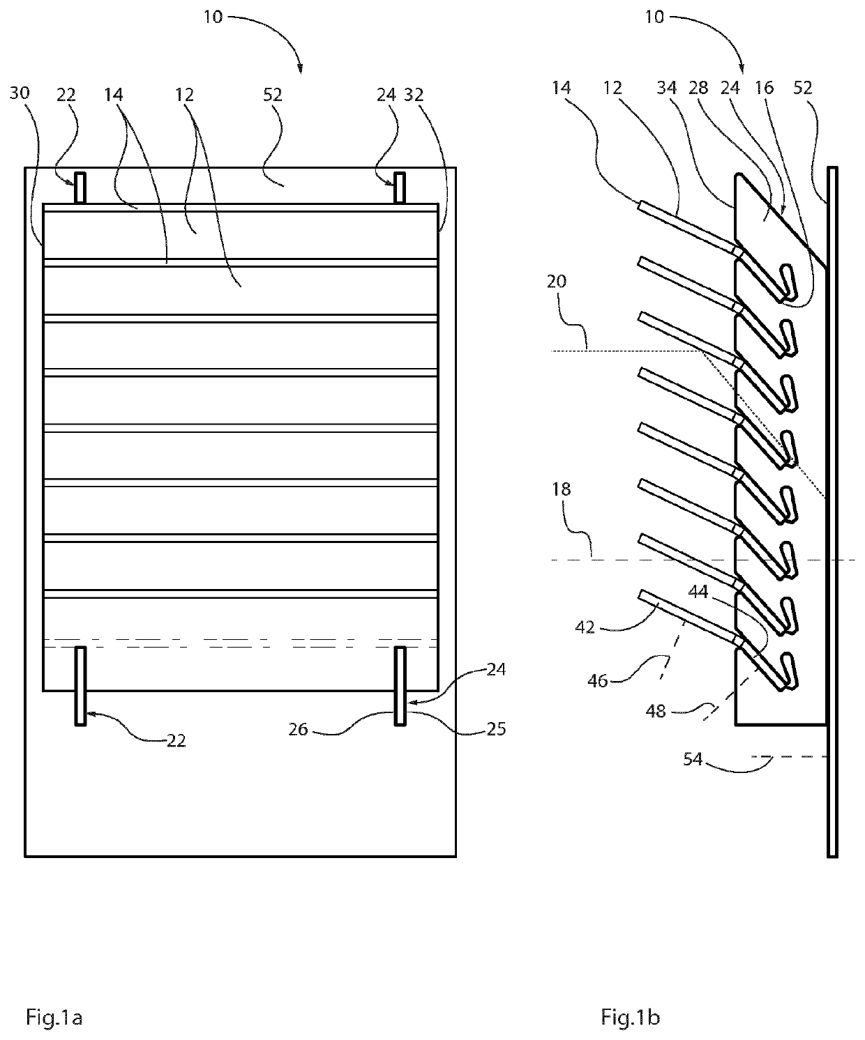
[0052]An embodiment of a slat arrangement 10 is illustrated in FIGS. 1a and 1b. The slat arrangement 10 has a number of steel slats 12 manufactured from 8 mm steel plates. This thickness is suitable for rifle ammunition, such as 7.62 / 10B. In other embodiments, the steel slats 12 are manufactured from 6.5 mm steel plates, which are suitable for pistol ammunition and lighter rifle ammunition, such as 9×19 39B and 5.56 5B. The steel slats 12 are positioned in a louver-like fashion, which means that they are parallel and slanted with respect to the normal 18 of the slat arrangement 10. The normal 18 is indicated by a dashed line in FIG. 1b, i.e. corresponding to a direction from right to left, or vice versa.

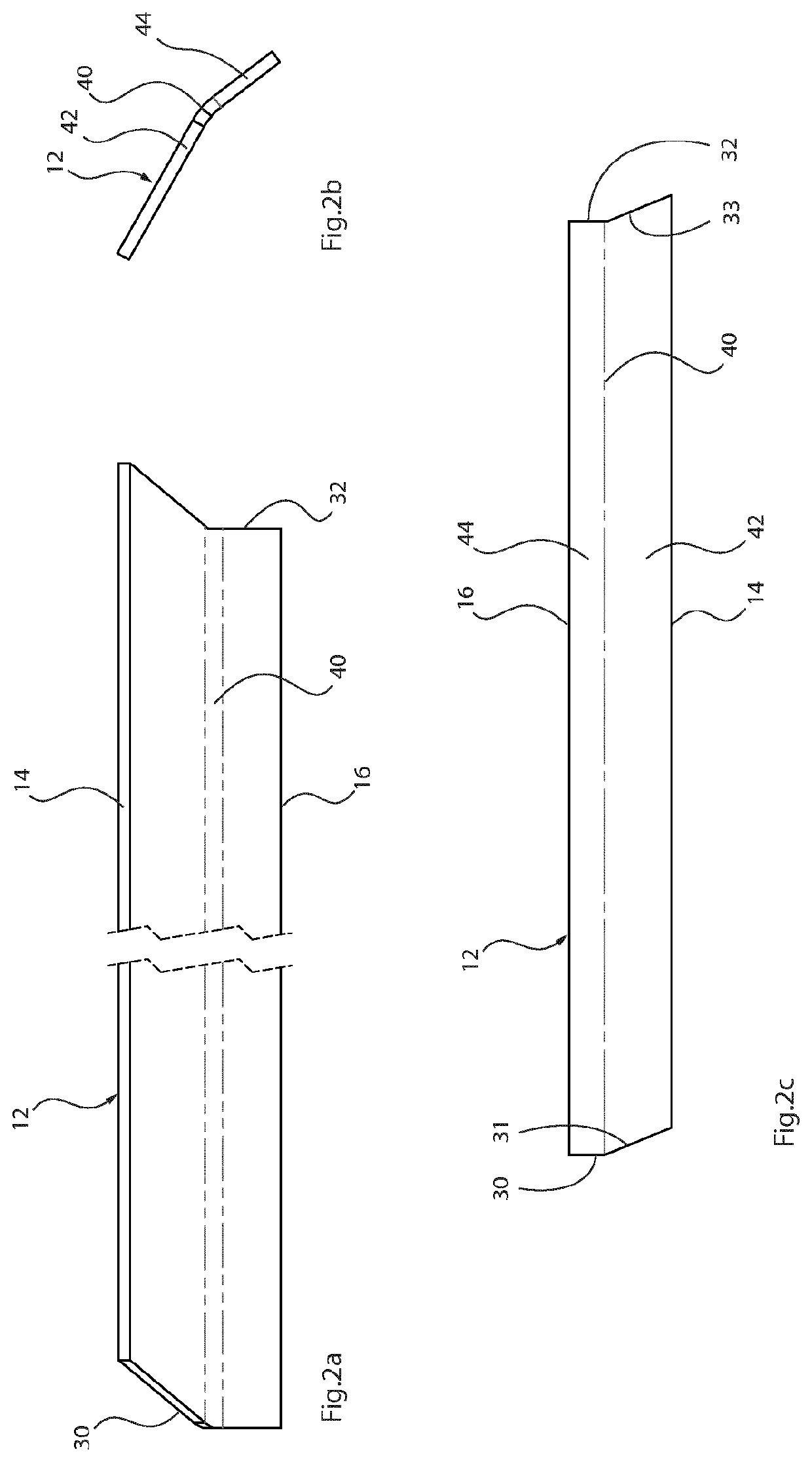
[0053]The separation between the front edges 14 is equal to the separation between the back edges 16 of neighboring steel slats 10. Also, as is shown in FIG. 1b, all pairs of neighboring steel slats have the same separations between them.

[0054]The front edges 14 of the steel slats 12...


PUM


Abstract

A slat arrangement for redirecting the trajectory of a bullet has a plurality of elongated steel slats, and each elongated steel slat has a longitudinal front edge and a longitudinal back edge stretching between a first end and a second end. The steel slats are positioned in a louver-like fashion for changing the direction of a bullet following a trajectory along the normal of the slat arrangement. A support structure is connected to each steel slat at the back edge of the steel slat, between the first end and the second end of the steel slat.

Description

CROSS-REFERENCE TO RELATED APPLICATION[0001]This application is a continuation of co-pending U.S. patent application Ser. No. 16 / 082,668, filed Sep. 6, 2018, which is a National Phase, under 35 U.S.C. § 371(c), of International Application No. PCT / EP2017 / 055433, filed Mar. 8, 2017, which claims priority from Swedish Application No. SE 1650319-5, filed Mar. 9, 2016. The disclosures of all of the referenced applications are incorporated herein by reference in their entireties.FEDERALLY SPONSORED RESEARCH OR DEVELOPMENT[0002]Not ApplicableTECHNICAL FIELD OF THE INVENTION[0003]The present invention relates generally to the field of bullet traps for shooting ranges, and in particular to bullet traps for indoor shooting ranges. Further, the present invention relates specifically to slat arrangements having steel slats positioned in a louver-like fashion for changing the direction of bullets.BACKGROUND OF THE INVENTION[0004]There are bullet traps for shooting ranges that have inclined stee...

Claims


Application Information

Patent Timeline
Patent Type & Authority Applications(United States)
IPC IPC(8): F41J13/00F41H5/02F41H5/013
CPCF41J13/00F41H5/013F41H5/026
Inventor NORMAN, PETER
Owner ODIN TARGET
Why Eureka
Try Eureka