Supercharge Your Innovation With Domain-Expert AI Agents!

Quick grip pocket hole jig system and method

a jig and pocket hole technology, applied in the direction of drill jigs, wrenches, metal-working equipment, etc., can solve the problems of not being well suited to various applications and leave much to be desired, and achieve the effect of convenient angular rotation of the clamp body, convenient quick gripping, and convenient repeating of the clamping of workpieces

Active Publication Date: 2020-07-30
KREG ENTERPRISES
View PDF0 Cites 2 Cited by
  • Summary
  • Abstract
  • Description
  • Claims
  • Application Information

AI Technical Summary

Benefits of technology

The present invention is a pocket hole jig system that includes a support section with a clamp support, an end stop, and a back stop. A clamping assembly is connected to the support section with a clamping rod that extends through the clamp support. A drill guide carrier with a drill guide assembly is connected to the clamping rod on a forward side of the clamp support. A quick grip clamp body with a trigger and a release mechanism is connected to the clamping rod on a rearward side of the clamp support. The clamp body facilitates quick gripping of a workpiece within the support section. The clamping assembly includes a return spring and a release mechanism such that when the release mechanism is actuated, the drill guide carrier and the drill guide assembly are automatically moved to a non-clamping position. A stroke limiter is connected to the clamping rod and limits the distance that the clamping rod will move so as to facilitate faster and easier repeat clamping of workpieces of similar size. The support section facilitates stable placement in both horizontal and vertical use. Overall, this improved pocket hole jig system provides efficient and effective clamping for drilling pocket holes.

Problems solved by technology

All of these configurations and manners of operation leave much to be desired.
In addition, all of the existing pocket hole jigs available have deficiencies and therefore are not well suited for various applications.

Method used


Image

  • Quick grip pocket hole jig system and method
  • Quick grip pocket hole jig system and method
  • Quick grip pocket hole jig system and method

Examples


Embodiment Construction

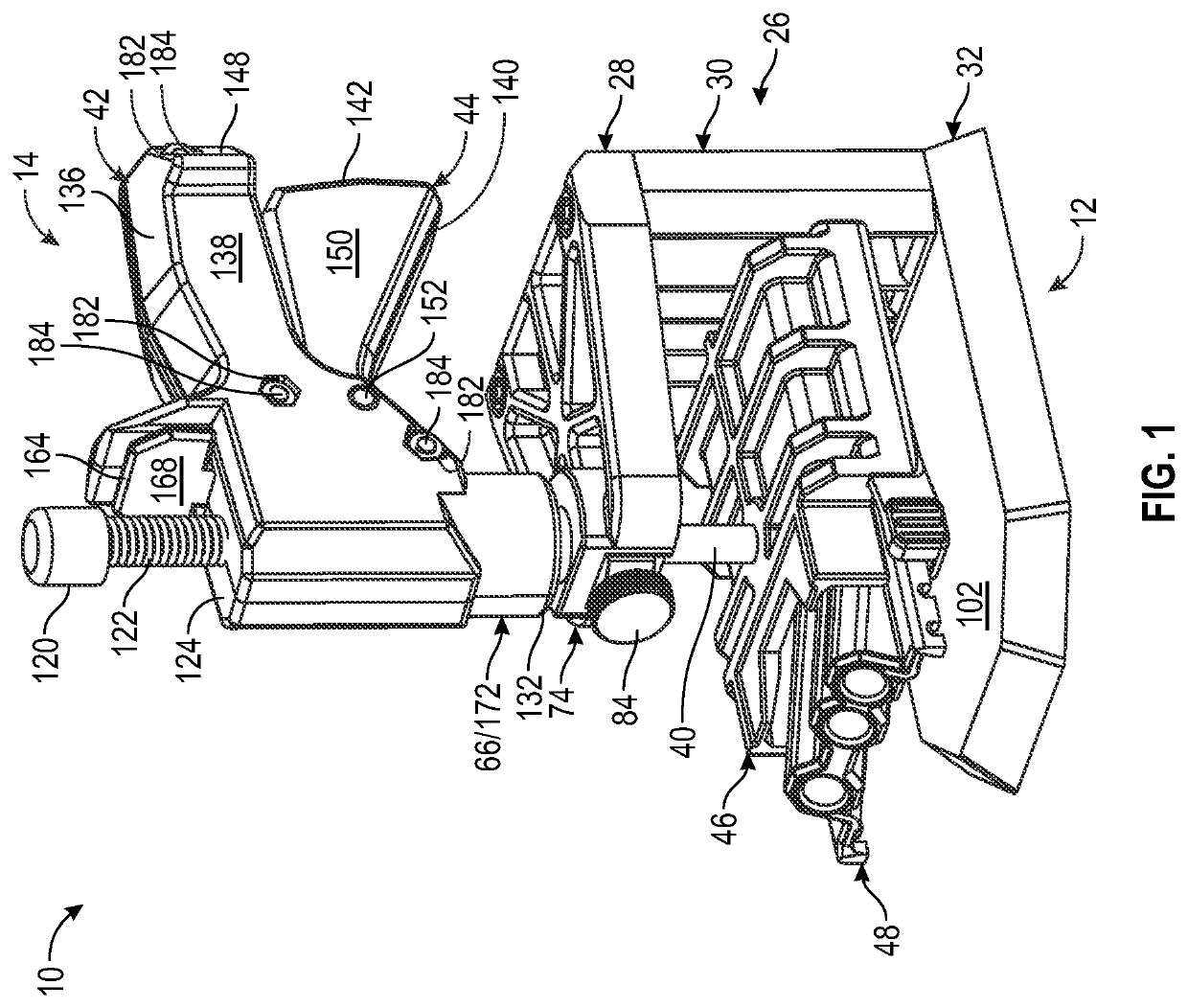
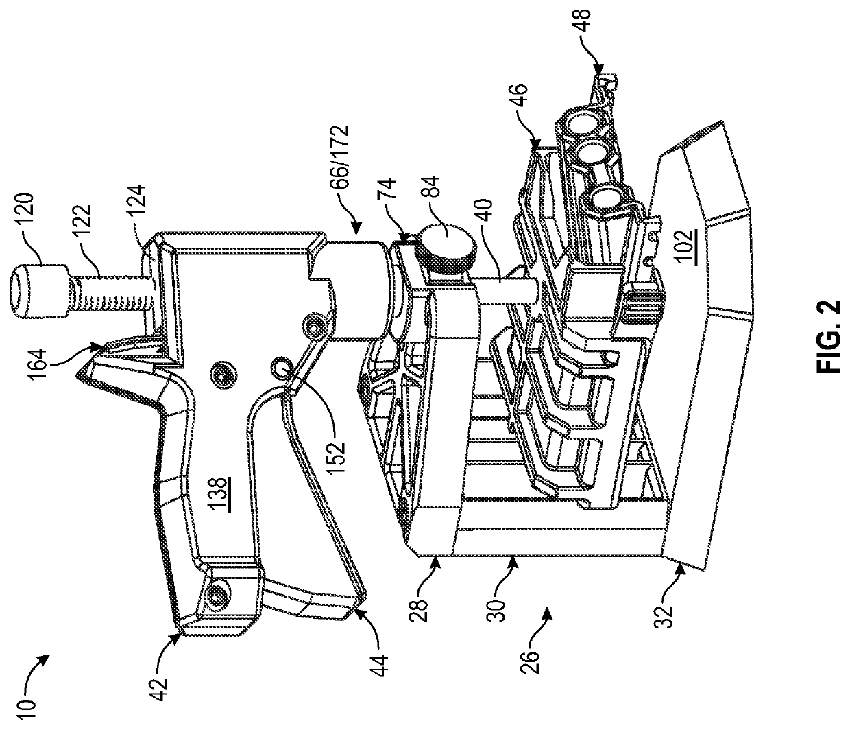
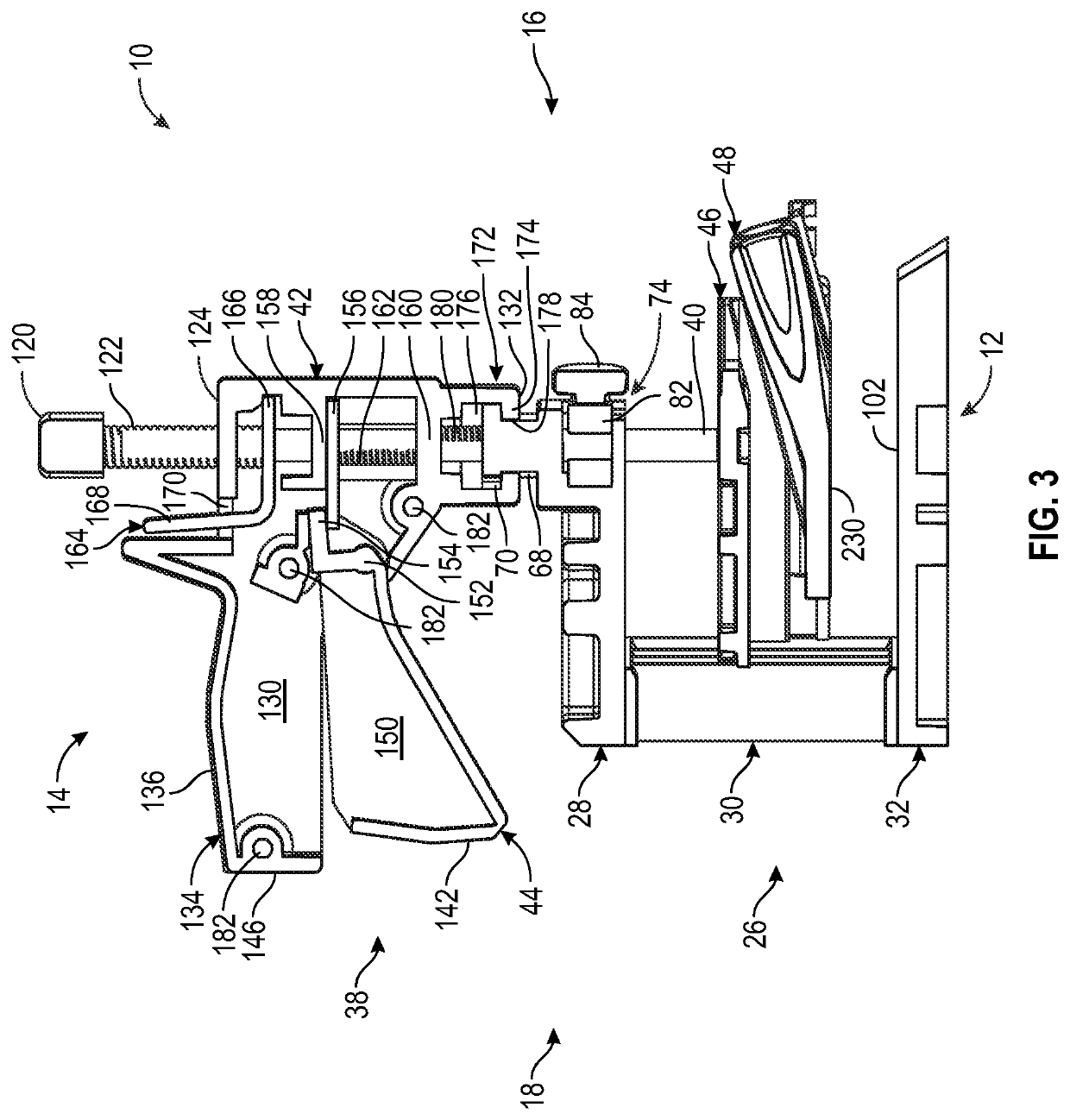
[0120]In the following detailed description of the embodiments, reference is made to the accompanying drawings which form a part hereof, and in which is shown by way of illustration specific embodiments in which the disclosure may be practiced. These embodiments are described in sufficient detail to enable those skilled in the art to practice the disclosure, and it is to be understood that other embodiments may be utilized and that mechanical, procedural, and other changes may be made without departing from the spirit and scope of the disclosure. The following detailed description is, therefore, not to be taken in a limiting sense, and the scope of the disclosure is defined only by the appended claims, along with the full scope of equivalents to which such claims are entitled.

[0121]As used herein, the terminology such as vertical, horizontal, top, bottom, front, back, end and sides are referenced according to the views presented. It should be understood, however, that the terms are ...


PUM

PropertyMeasurementUnit
Angleaaaaaaaaaa
Lengthaaaaaaaaaa
Distanceaaaaaaaaaa

Abstract

A quick grip pocket hole jig system is presented having a support section having a clamp support, an end stop and a back stop. A clamping assembly is connected to the support section having a clamping rod that extends through the clamp support. A drill guide carrier having a drill guide assembly is connected to the clamping rod on a forward side of the clamp support. A clamp body having a trigger and a release mechanism is connected to the clamping rod on a rearward side of the clamp support. The clamp body is a quick grip clamp body that facilitates quick gripping of a workpiece positioned within the support section. The clamping assembly includes a return spring and a release mechanism such that when the release mechanism is actuated the drill guide carrier and the drill guide assembly are automatically moved to a non-clamping position.

Description

CROSS REFERENCE TO RELATED APPLICATIONS[0001]This application claims benefit from U.S. Provisional Application No. 62 / 797,492 which was filed Jan. 28, 2019, the entirety of which is incorporated herein fully by reference.FIELD OF THE DISCLOSURE[0002]This disclosure relates generally to jig systems for holding workpieces. More specifically and with out limitation, this disclosure relates generally to an improved drilling jig systems that facilitate faster and / or easier clamping of workpieces.BACKGROUND OF THE DISCLOSURE[0003]Pocket hole wood joinery involves joining boards by inserting a fastener at an angle through the edge of one workpiece into an adjoining workpiece, thereby joining the two workpieces together. Such joints are commonly used for face frames, cabinet boxes, leg-to-rail joinery in chairs and tables, and so forth. Drill guides or jigs are used to drill the holes through which the fasteners or pocket screws are inserted into the adjoining workpiece.[0004]To facilitate ...

Claims


Application Information

Patent Timeline
IPC IPC(8): B23B47/28B25B5/12
CPCB23B47/287B23B2247/10B23B2247/12B23B2260/03B25B5/125B25B5/02B25B5/06B25B5/003B25B5/101B25B23/08B25B23/04
Inventor FORBES, TIMOTHY J.SCHAAF, SCOTTMCCLELLAN, MARK DAVID
Owner KREG ENTERPRISES
Features
  • R&D
  • Intellectual Property
  • Life Sciences
  • Materials
  • Tech Scout
  • Unparalleled Data Quality
  • Higher Quality Content
  • 60% Fewer Hallucinations
Learn More