
Gas detection element

Active Publication Date: 2020-08-06
NITTO DENKO CORP
View PDF0 Cites 0 Cited by
  • Summary
  • Abstract
  • Description
  • Claims
  • Application Information

AI Technical Summary

Benefits of technology

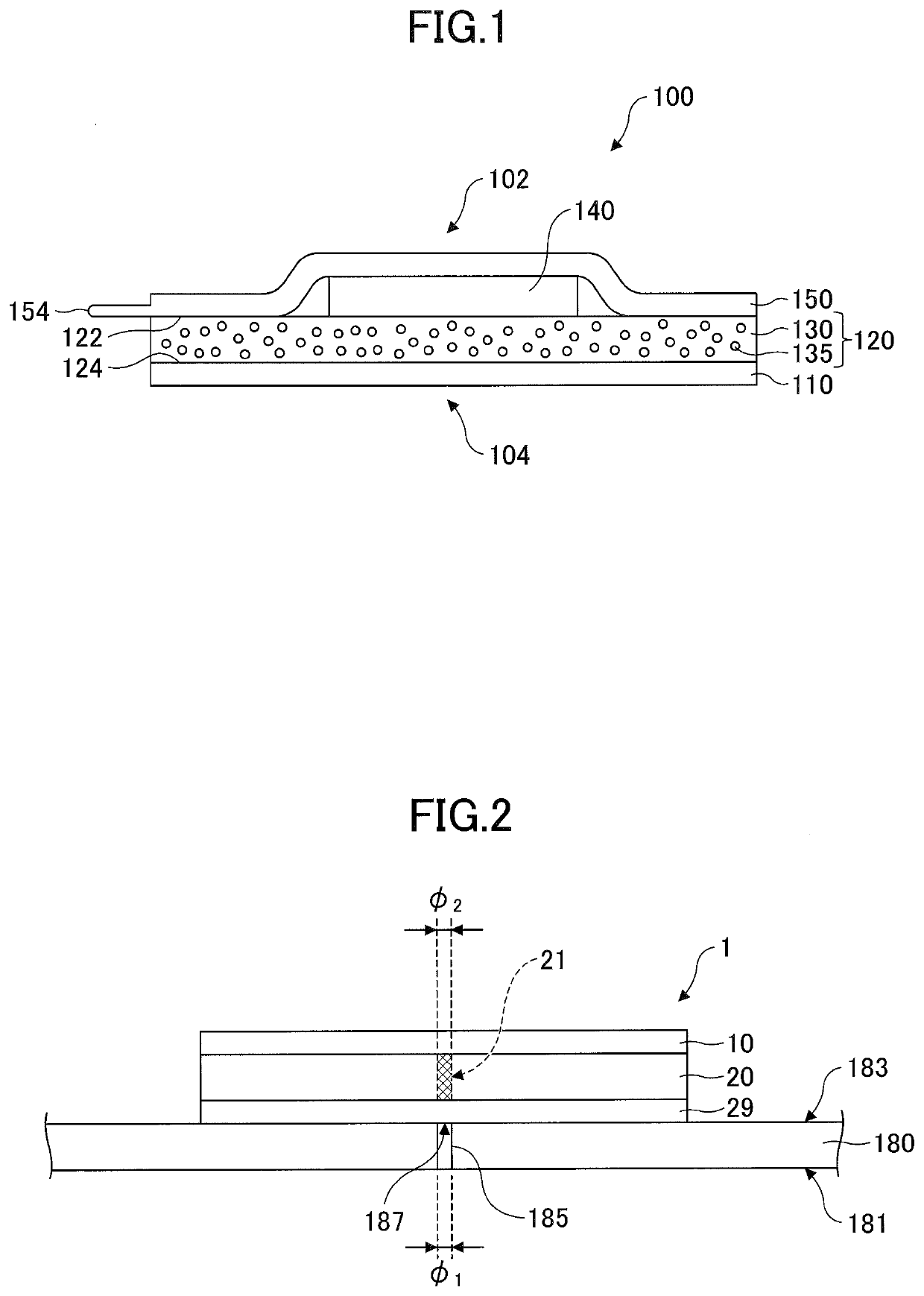
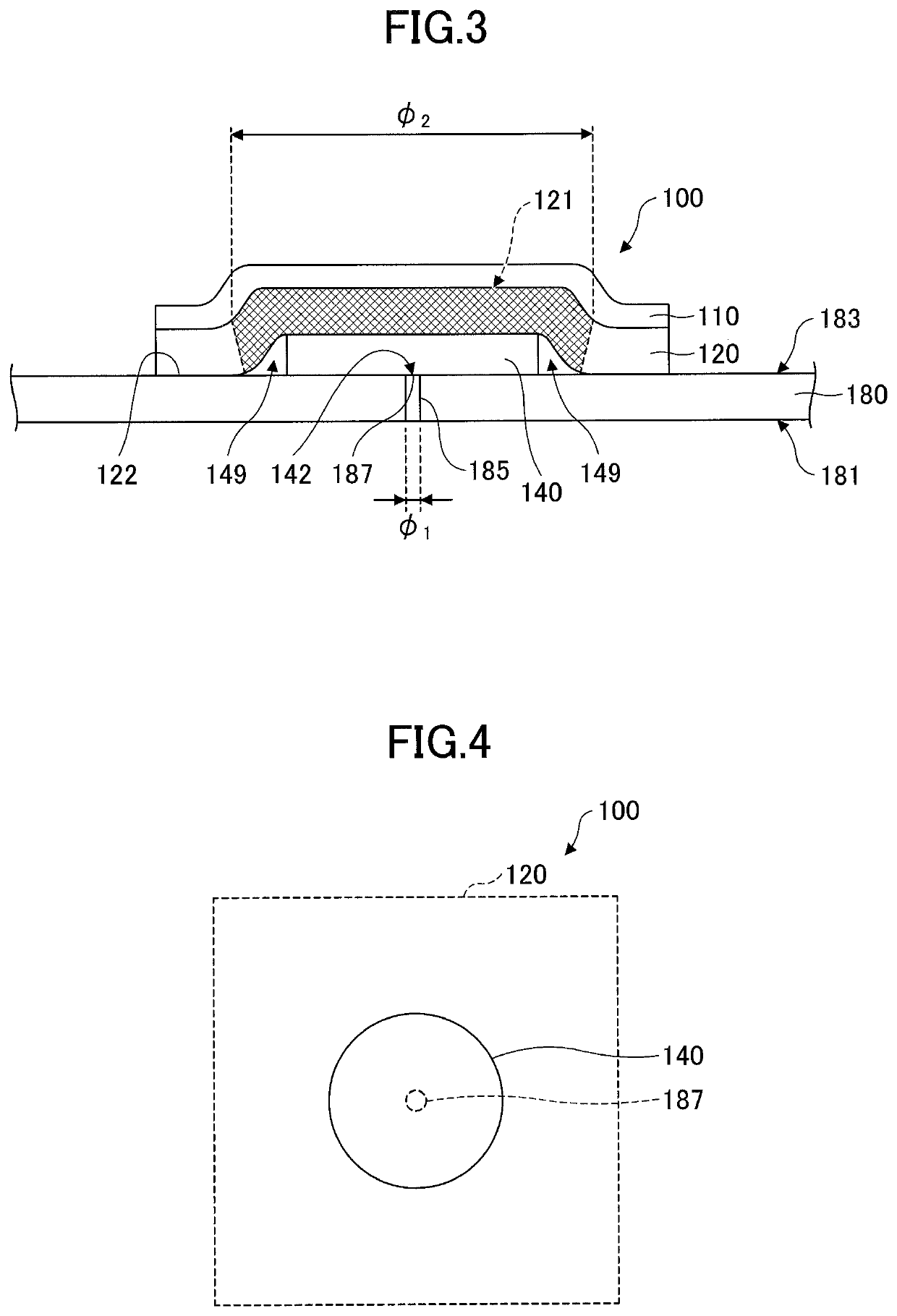
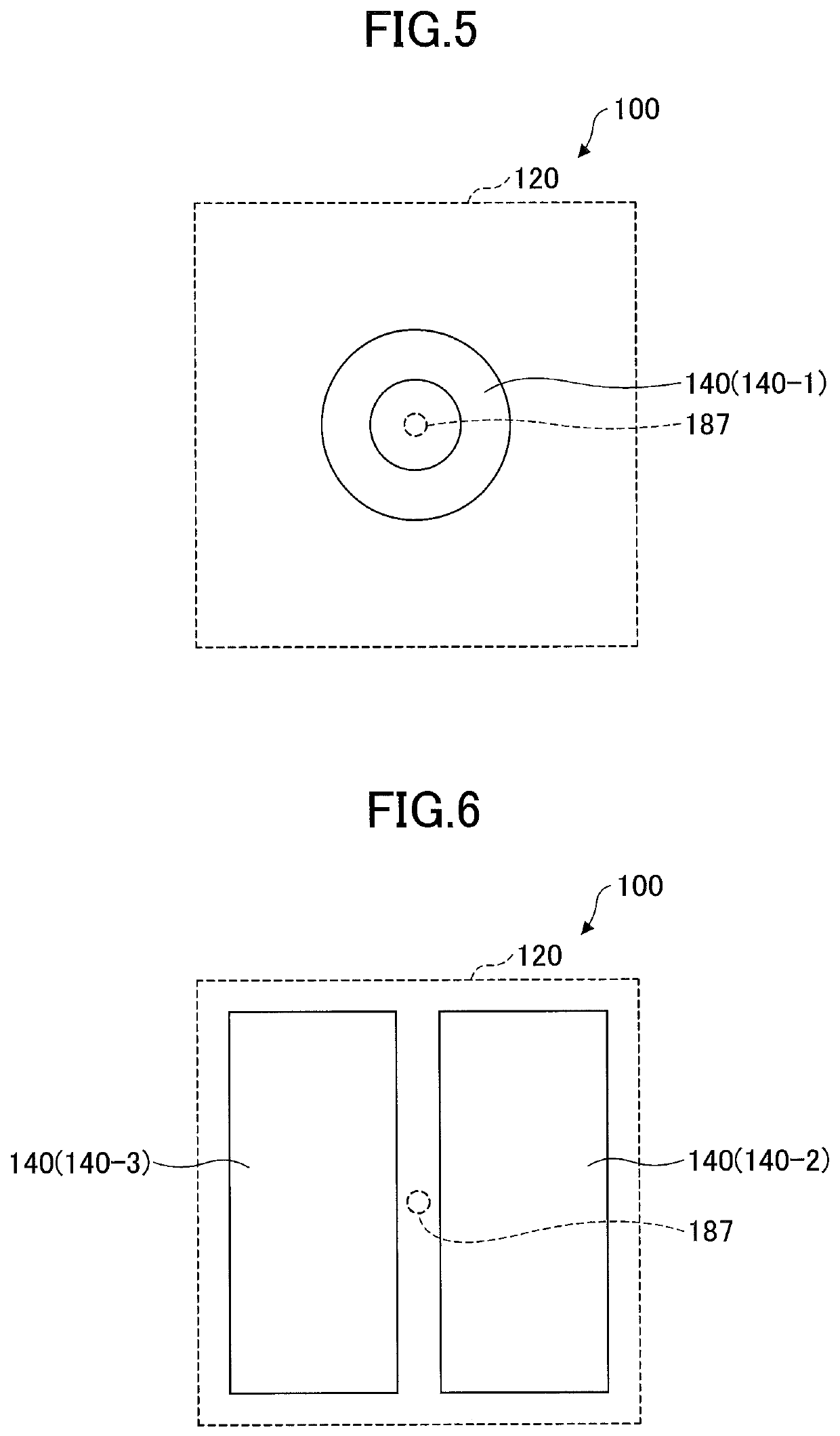
The patent describes a gas detection element that helps to make it easier to see when gas leaks.

Problems solved by technology

Of these methods, the method using soap water requires complicated measurement preparation, and also has difficulty in determining the presence of gas bubbles if the amount of hydrogen gas leakage is small.
Therefore, the detection accuracy is poor in the method using soap water.
Further, the method using the hydrogen sensor is susceptible to the flow of air in a measurement environment, thus resulting in a decrease in reliability.
In addition, the method using the hydrogen sensor has difficulty in identifying the accurate location of leakage.

Method used


Image

  • Gas detection element
  • Gas detection element
  • Gas detection element

Examples


example 1

[0241]A gas detection element was manufactured by the following method.

[0242]The gas detection element had a configuration including a backing, an undercoat layer, a gas detection layer including a chemochromic pigment, and a spacer in the stated order.

(Preparing Backing and Spacer)

[0243]As the backing, polyimide (Kapton) (Dupont High Performance Films Circleville, Ohio, USA) having a thickness of 25 μm was prepared.

[0244]As the spacer, a non-woven fabric (HOP-60HCF(170); Hirose Paper Mfg Co., Ltd.) with 10 mm in length and 10 mm in width was prepared. The thickness of the non-woven fabric is approximately 164 μm.

[0245]The Gurley method was used to evaluate the air permeability of the spacer. For measurement, a Gurley type densometer (No. 323-AUTO; manufactured by Yasuda Seiki) was used, and the measurement was performed in accordance with JIS P8117.

[0246]As a result of the measurement, the air permeability of the spacer was 0.06 sec / 100 cm3.

(Coating Liquid for Undercoat Layer)

[0247...

example 2

[0270]A patch-type gas detection element (hereinafter referred to as a “sample 2”) was manufactured by a method similar to that of Example 1.

[0271]However, in Example 2, two non-woven fabrics were stacked and used as a spacer. Thus, the thickness of the spacer was 328 μm.

[0272]The air permeability of the spacer was measured by the above-described method. The air permeability of the spacer was 0.11 sec / 100 cm3.

example 3

[0273]A gas detection element was manufactured by a method similar to that of Example 1.

[0274]However, in Example 3, a silicone-based thermal diffusion sheet (EX40015DS; manufactured by Dexerials Corporation) having a thickness of approximately 150 μm was used as a spacer.

[0275]Accordingly, a patch-type gas detection element (hereinafter referred to as a “sample 3”) was obtained.


PUM

PropertyMeasurementUnit
Thicknessaaaaaaaaaa
Thicknessaaaaaaaaaa
Fractionaaaaaaaaaa

Abstract

A gas detection element for detection of a measurement target gas is provided. The gas detection element includes a gas detection layer including a chemochromic pigment; and a spacer. The spacer is permeable to the measurement target gas, is disposed on a first surface of the gas detection layer, and has an area smaller than an area of the gas detection layer.

Description

TECHNICAL FIELD[0001]The present application relates to a gas detection element.BACKGROUND ART[0002]Hydrogen gas is used in various applications, including energy generation means such as batteries, energy storage means, and energy transfer means.[0003]Hydrogen gas is a colorless, odorless, and flammable gas having a wide flammability limit in the air. Therefore, it is required to properly detect hydrogen gas leakage for safety purposes in any environment and / or apparatus in which hydrogen gas is handled.[0004]In the past, methods using soapy water and a hydrogen sensor have been employed to detect hydrogen gas leakage.[0005]Of these methods, the method using soap water requires complicated measurement preparation, and also has difficulty in determining the presence of gas bubbles if the amount of hydrogen gas leakage is small. Therefore, the detection accuracy is poor in the method using soap water. Further, the method using the hydrogen sensor is susceptible to the flow of air in ...

Claims


Application Information

Patent Timeline
IPC IPC(8): G01N21/78G01N33/00G01N31/22
CPCG01N33/005G01N31/223G01N21/783C09D183/04G01N2021/773G01N31/224G01N31/22C08L83/00
Inventor SUZUKI, NAMIKOHIGUCHI, HIROYUKINAKAMURA, KOICHINISHIGAWARA, MASAYAMOHAJERI, NAHID
Owner NITTO DENKO CORP
Learn More