Sliding mechanism for guide pins of a disc brake assembly

Pending Publication Date: 2020-08-13
ZF ACTIVE SAFETY US INC
View PDF1 Cites 4 Cited by
  • Summary
  • Abstract
  • Description
  • Claims
  • Application Information

AI Technical Summary

Benefits of technology

[0006]According to one aspect of the invention, a disc brake assembly comprises an anchor bracket having at least one bore formed therein, a guide pin adapted to be disposed in the at least one bore and slidably support a brake caliper relative t

Problems solved by technology

However, as the braking torque increases, and therefore anchor bracket deflection, the guide pins may bind against the anchor bracket in the bores and reduce an ability of the brake caliper to maintain or produce equal pressure on each of the brake pads.
This can lead to uneven wear of the brake disc and the brake pads, and produce undesirable effects related noise, vibration and h

Method used


Image

  • Sliding mechanism for guide pins of a disc brake assembly
  • Sliding mechanism for guide pins of a disc brake assembly
  • Sliding mechanism for guide pins of a disc brake assembly

Examples


first embodiment

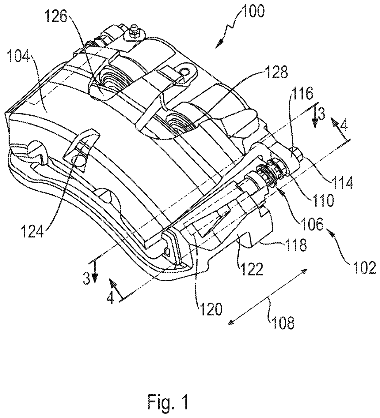
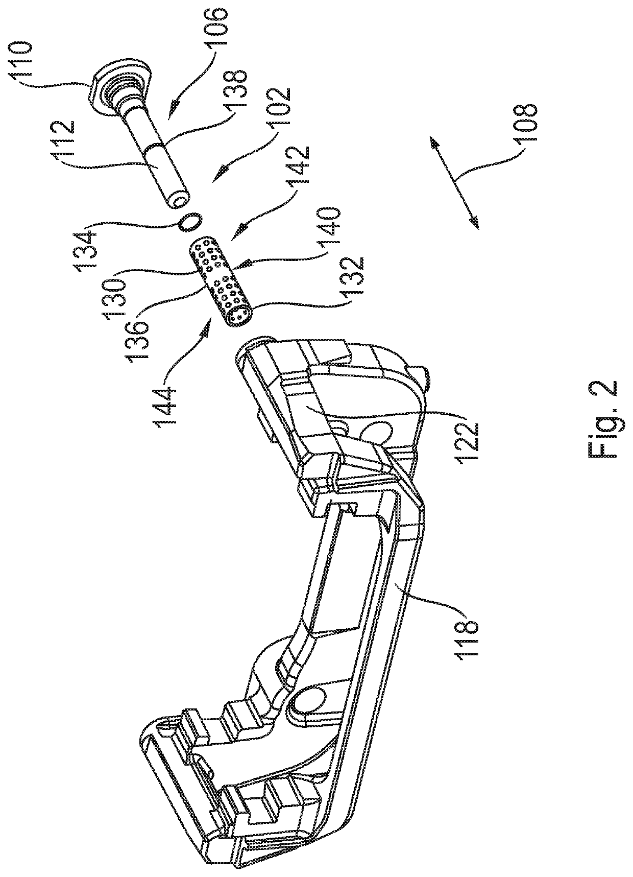
[0027]Referring now to FIG. 1, there is illustrated a disc brake assembly, indicated generally at 100, having a sliding mechanism, indicated generally at 102 (no 102 shown in FIG. 1) and shown in FIG. 2, in accordance with the present invention. The disc brake assembly 100 is a “pin guided” or “pin sliding” type of which the general structure and operation is well known in the prior art. For example, the disc brake assembly 100 may be such as is disclosed by U.S. Pat. No. 8,844,683 to Sternal et al., U.S. Pat. No. 8,051,958 to Rockwell et al., U.S. Pat. No. 6,039,156 to Schneider, U.S. Pat. No. 5,927,446 to Evans, U.S. Patent Application Publication No. 2017 / 0261053 to Schaefer et al., or U.S. Patent Publication No. 2018 / 0087589 to Gerber et al, the disclosures of all of which are hereby incorporated by reference in entirety herein. Furthermore, the sliding mechanism 102 may be used in connection with other types of pin guided or pin sliding disc brake assemblies if so desired.

[0028...

second embodiment

[0049]Referring now to FIG. 9, there is illustrated a sliding mechanism, indicated generally at 202, that is in accordance with the present invention. The sliding mechanism 202 is a variation of the sliding mechanism 102 described with reference to FIGS. 1-7. As such, like reference numerals, increased by 100, designate corresponding parts in the drawings and detailed description thereof will be omitted, unless otherwise noted.

[0050]The sliding mechanism 202 has bearing members 234 positioned by a tubular sleeve 232 in a spiral or corkscrew pattern. The spiral pattern is around an axis 272 along which a guide pin 206 extends. The spiral pattern increases structural durability of the sliding mechanism 202.


PUM


Abstract

A disc brake assembly includes an anchor bracket, a guide pin, a sliding mechanism, and a damping member. The anchor bracket may have at least one bore formed therein. The guide pin may be adapted to be disposed in the at least one bore and slidably support a brake caliper relative to the anchor bracket. The sliding mechanism may be adapted to be disposed in the at least one bore and to slidably support the guide pin in the at least one bore. The damping member may damp sliding motion of the guide pin relative to the anchor bracket.

Description

CROSS-REFERENCE TO RELATED APPLICATIONS[0001]This application claims priority to U.S. Provisional Patent Application No. 62 / 804,387, filed Feb. 12, 2019, the present disclosure of which is incorporated herein by reference in its entirety.BACKGROUND OF INVENTION[0002]This invention relates in general to vehicle disc brake assemblies and in particular to a sliding mechanism for use with guide pins of a disc brake assembly.[0003]Most vehicles are equipped with a brake system for slowing or stopping movement of the vehicle in a controlled manner A typical brake system for an automobile or light truck includes a disc brake assembly for each of the front wheels and either a drum brake assembly or a disc brake assembly for each of the rear wheels. The brake assemblies are actuated by hydraulic or pneumatic pressure generated when an operator of the vehicle depresses a brake pedal. The structures of these drum brake assemblies and disc brake assemblies, as well as the actuators thereof, are...

Claims


Application Information

Patent Timeline
IPC IPC(8): F16D65/00F16D55/2265
CPCF16D55/22655F16D65/0006F16D2055/0008F16D65/0093F16D65/0087F16D2055/0041F16D65/0056F16D2055/007
Inventor WILLEY, JOSEPH
Owner ZF ACTIVE SAFETY US INC
Why Eureka
Try Eureka