Laser radar, and light receiving method of laser radar

a laser radar and laser radar technology, applied in the direction of measuring devices, using reradiation, instruments, etc., can solve the problems of reducing reception sensitivity, prone to reliability, and device not directly contributing to enhancing reception sensitivity, so as to achieve high sensitivity measurement

Active Publication Date: 2020-08-13
TOYOTA CENT RES & DEV LAB INC
View PDF0 Cites 9 Cited by
  • Summary
  • Abstract
  • Description
  • Claims
  • Application Information

AI Technical Summary

Benefits of technology

[0009]In consideration of the above issues, an object of the present invention is to implement a laser radar device with which high sensitivity measurements are possible and that is highly reliable, and to implement an optical reception method for a laser radar device of the same.
[0023]According to the present invention, an advantageous effect is exhibited of high sensitivity measurement being possible when implementing a highly reliable laser radar device and an optical reception method of a laser radar device.

Problems solved by technology

Issues related to reliability are liable to arise in such cases, since the mirror or prism includes movable components.
Moreover, there is also an issue in configurations using a mirror or prism in that optical defects may arise, leading to a reduction in reception sensitivity.
Thus this device does not directly contribute to enhancing reception sensitivity that is one attribute demanded in a laser radar device.

Method used


Image

  • Laser radar, and light receiving method of laser radar
  • Laser radar, and light receiving method of laser radar
  • Laser radar, and light receiving method of laser radar

Examples


first exemplary embodiment

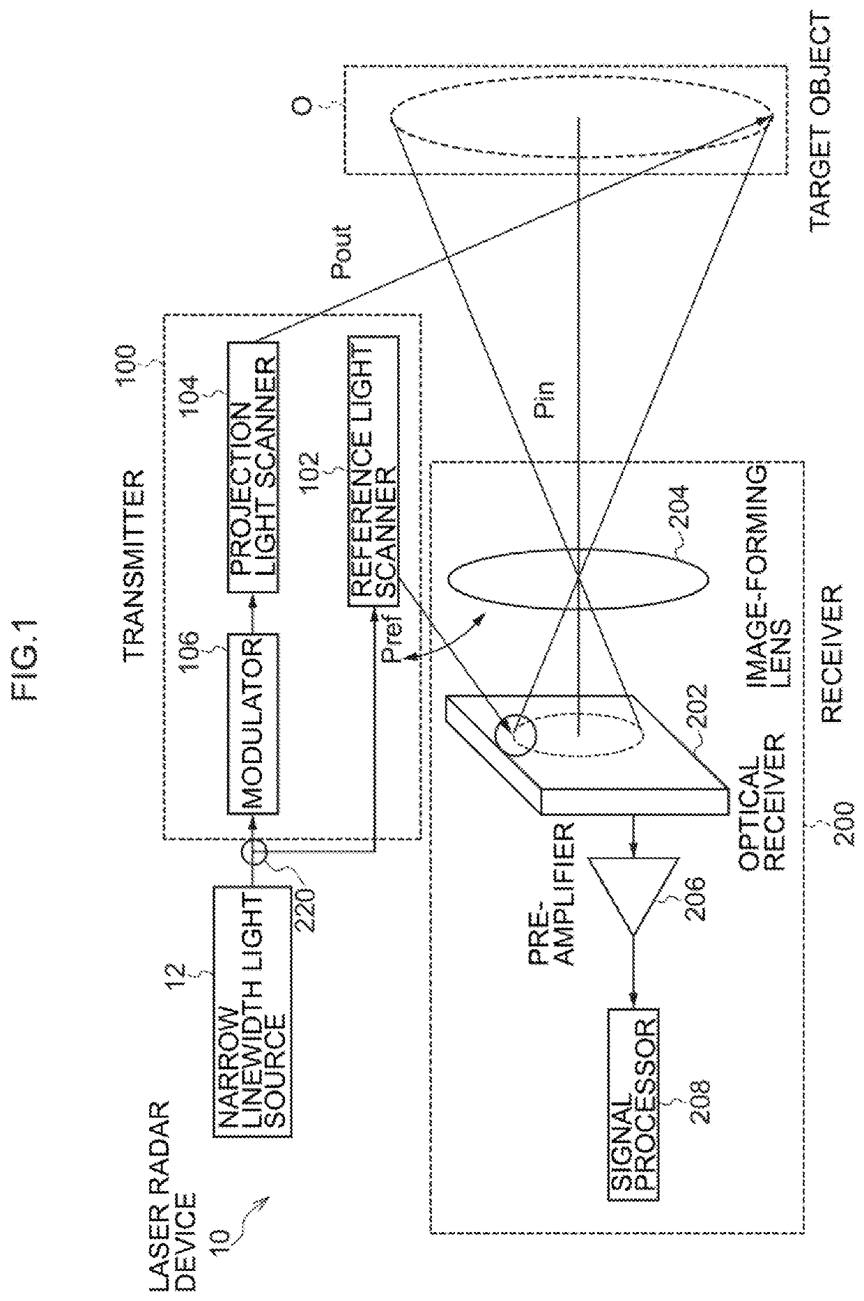
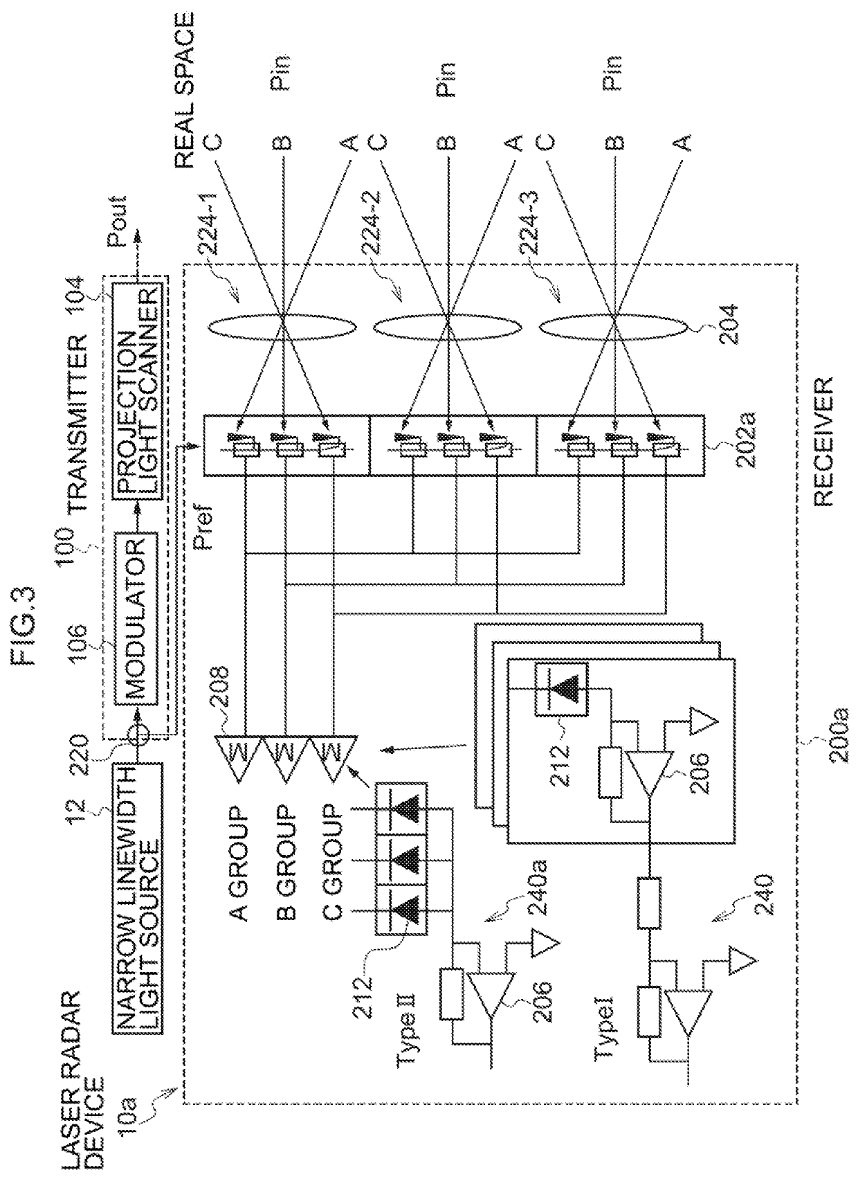
[0049]Explanation follows regarding a laser radar device 10a according to an exemplary embodiment, with reference to FIG. 2 to FIG. 4.

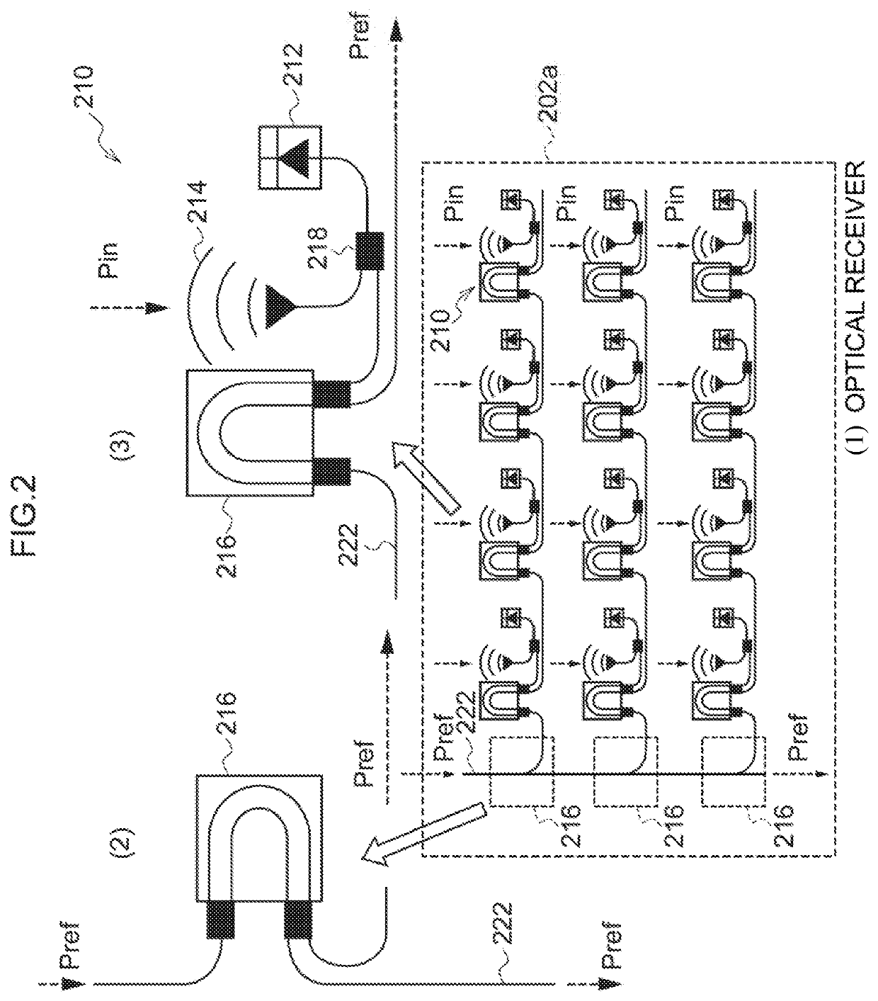
[0050]First, explanation follows regarding an optical receiver 202a according to the present exemplary embodiment, with reference to FIG. 2. As illustrated in (1) of FIG. 2, the optical receiver 202a includes plural of the unit optical reception sections 210 disposed in an array. The number of the unit optical reception sections 210 that configure the optical receiver 202a is, as an example, 50×50=2500 units. However, only 3×4=12 units thereof are illustrated in (1) of FIG. 2.

[0051]As illustrated in (1) of FIG. 2, the reference light Pref incident from one end of an optical waveguide 222 is switching controlled between guiding and not guiding by an optical switch 216 illustrated in (2) of FIG. 2, and is distributed to the respective unit optical reception sections 210. Reception light Pin corresponding to each portion of the target object O is inciden...

second exemplary embodiment

[0064]Explanation follows regarding the laser radar device 10 according to the present exemplary embodiment, with reference to FIG. 5. The present exemplary embodiment is a mode that employs an optical receiver 202b as the optical receiver 202 of the laser radar device 10 illustrated in FIG. 1.

[0065]As illustrated in FIG. 5, the optical receiver 202b employs optical receivers 210a that are obtained by removing the optical switch 216 from the unit optical reception section 210 in place of the unit optical reception sections 210 of the optical receiver 202a illustrated in (1) of FIG. 2.

[0066]The optical receiver 202a illustrated in (1) of FIG. 2 is a mode that switches as to whether or not the reference light Pref is caused to be incident to each of the photodiodes 212; however, in the optical receiver 202b a mode is adopted in which the optical switches 216, disposed at a left end, switch as to whether or not the reference light Pref is caused to be incident to each of the arrayed ph...

third exemplary embodiment

[0068]Explanation follows regarding a laser radar device 10b according to an exemplary embodiment, with reference to FIG. 6 to FIG. 8. The present exemplary embodiment is a mode that employs an optical receiver 202c as the optical receiver 202, by employing a receiver 200b as the receiver 200 of the laser radar device 10 illustrated in FIG. 1.

[0069]As illustrated in (1) of FIG. 6, in place of the unit optical reception sections 210a of the optical receiver 202b illustrated in FIG. 5, the optical receiver 202c employs unit optical reception sections 210b that each integrate together a photodiode (PD) and a transimpedance amplifier (TIA) serving as a pre-amplifier. Configuration in which whether or not the reference light Pref is caused to be incident to the photodiodes PD is implemented by switching, using the optical switches 216 disposed at the left end of the optical receiver 202c in row units of the unit optical reception section 210b laid out in an array, is similar to that of t...


PUM


Abstract

A laser radar device includes: a light source; a projection light scanner that scans one part of light split off from emission light of the light source, and that generates transmission light for radiating onto a target object; an image forming section that forms plural respective reception lights of the transmission light reflected by respective locations of the target object into an image on a single flat plane as plural image-formation points; an optical receiver that is disposed at the plural image-formation points, and that includes plural unit optical reception sections for mixing each of the plural reception lights together with a reference light and performing optical heterodyne detection; and a reference light scanner that scans or distributes another light split off from the emission light from the light source, and that generates the reference light for radiating onto each of plural of the unit optical reception sections.

Description

CROSS-REFERENCE TO RELATED APPLICATION[0001]This application is based on and claims priority under 35 USC 119 from Japanese Patent Application No. 2014-234987 filed on Nov. 19, 2014, the disclosure of which is incorporated by reference herein.BACKGROUNDTechnical Field[0002]The present invention relates to a laser radar device and an optical reception method for a laser radar device.Related Art[0003]A laser radar device is a type of remote sensing technology that employs light, and is a device in which the distance to a faraway target object, properties of the target object, and the like are analyzed by radiating light from pulse-emitting light projector onto the target object, and measuring scattered light that has been reflected by the target object and received by an optical receiver.[0004]Examples of such laser radar devices include a device described by Japanese Patent Application Laid-Open (JP-A) No. 2000-338243. The laser radar device described by JP-A No. 2000-338243 includes...

Claims


Application Information

Patent Timeline
Patent Type & Authority Applications(United States)
IPC IPC(8): G01S17/34G01S7/4911G01S7/4912G01S17/02G01S17/32
CPCG01S7/4911G01S17/34G01S7/4917G01S17/32G01S7/4817G01S17/42G01S17/02
Inventor INOUE, DAISUKEICHIKAWA, TADASHIYAMASHITA, TATSUYANAKAO, AKARIHASEGAWA, KAZUO
Owner TOYOTA CENT RES & DEV LAB INC
Why Eureka
Try Eureka