
Reeling Shaft Transfer Rail System and Method of Transferring Reeling Shafts on a Reeling Shaft Transfer Rail System

a transfer rail and reeling shaft technology, applied in mechanical conveyors, transportation and packaging, thin material processing, etc., can solve the problems of extremely dangerous domino-effect type and possible colliding effect, and achieve the effect of preventing domino-effect disadvantage in known systems, simple and light-weight transfer rail systems, and easy and accurate completion

Active Publication Date: 2020-08-20
VALMET TECH OY
View PDF0 Cites 0 Cited by
  • Summary
  • Abstract
  • Description
  • Claims
  • Application Information

AI Technical Summary

Benefits of technology

The present invention is a new transfer rail system for transferring reeling shafts that is designed to be simple, flexible, and cost-effective. This system is particularly useful in the production of fiber webs. The invention solves disadvantages and problems of prior art systems and provides an improved method for transferring reeling shafts on a transfer rail system. The transfer rail system uses an at least partially pressurized hose to prevent pressure release from under the reeling shaft by passage of fluid. The compression pressure of the hose can be adjusted to ensure effective compression and prevent leakage of the pressure medium. The transfer rail system is designed to synchronize the movement of the reeling shaft ends and can accommodate multiple reeling shafts simultaneous movement. The invention eliminates the need for moving actuators or energy transfer devices and provides increased safety due to the low-speed requirement for the desired movements of the reeling shafts.

Problems solved by technology

Further, also sometimes there has been a possibility of a colliding effect, in case too many reeling shafts have been on the transfer rails simultaneously or the stopping has not been functioning correctly.
Especially in the case of parent rolls this type of domino-effect is extremely dangerous due to their size and weight.
Also, the direction of movement of the reeling shafts has been fixed in some types of the known transfer rail systems, for example in transfer rail systems with inclined transfer rails without carriage arrangements for transfer of the reeling shafts, as the configuration does not allow movement backwards.

Method used


Image

  • Reeling Shaft Transfer Rail System and Method of Transferring Reeling Shafts on a Reeling Shaft Transfer Rail System
  • Reeling Shaft Transfer Rail System and Method of Transferring Reeling Shafts on a Reeling Shaft Transfer Rail System

Examples


Embodiment Construction

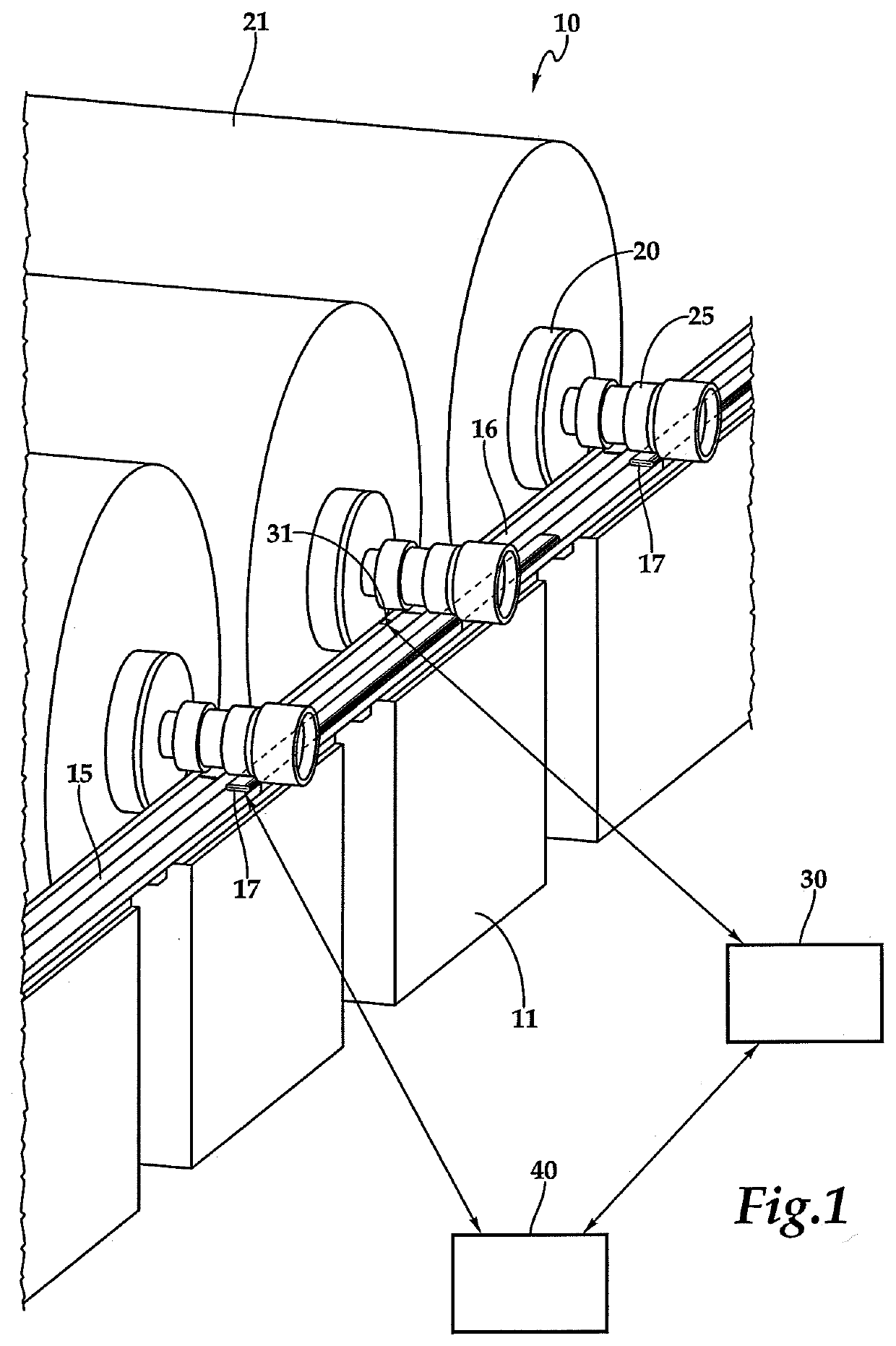
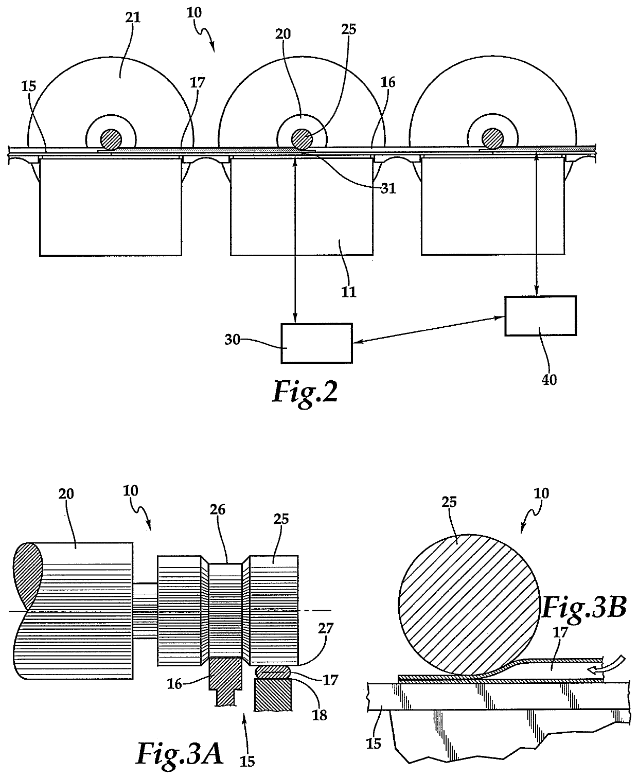
[0041]During the course of the following description relating to FIGS. 1-3B like numbers and signs will be used to identify like elements according to the different views which illustrate the invention and its advantageous examples. In the figures some repetitive reference signs have been omitted for clarity.

[0042]In FIG. 1 is shown a schematic example of a reeling shaft transfer rail system 10. The reeling shaft transfer rail system 10 is built on a frame 11. The frame 11 supports the reeling shafts 20 at each end of the reeling shaft 20. In FIG. 1 is shown only one end of the reeling shaft 20 and only one side of the reeling shaft rail system but it is to be understood that at the other end of the reeling shaft 20 a corresponding arrangement is located and thus the reeling shaft transfer rail system 10 comprises corresponding elements, structures etc. at each end of the reeling shaft 20 i.e. at each side of the transfer rail system 10. On the frame a transfer rail 15 is located, o...


PUM

PropertyMeasurementUnit
Fractionaaaaaaaaaa
Angleaaaaaaaaaa
Timeaaaaaaaaaa

Abstract

A reeling shaft transfer rail system has two parallel substantially horizontal or slightly sloped rails for supporting the ends (25) of a reeling shaft (20). Hoses are arranged on each of the transfer rails (15) and filled or drained to move and hold the reeling shaft (20). In a method of transferring reeling shafts on transfer rails, the reeling shafts (20) are transferred on two parallel, substantially horizontal or slightly downstream of a main transfer direction inclined transfer rails (15) for supporting each of the supporting ends (25) of a reeling shaft (20). The reeling shafts (20) are transferred or positioned in the reeling shaft transfer rail system (10) by pressurizing hoses (17) arranged on each of the transfer rails. The hoses are arranged so fluid added to or withdrawn from the hoses pushes or holds the reeling shaft (20) on the transfer rails (15).

Description

CROSS REFERENCES TO RELATED APPLICATIONS[0001]This application claims priority on EP 19157656 filed Feb. 18, 2019, the disclosure of which is incorporated by reference herein.STATEMENT AS TO RIGHTS TO INVENTIONS MADE UNDER FEDERALLY SPONSORED RESEARCH AND DEVELOPMENT[0002]Not applicable.BACKGROUND OF THE INVENTION[0003]The invention relates to a reeling shaft transfer rail system and to transferring reeling shafts on a reeling shaft transfer rail system.[0004]As known from the prior art fiber web producing processes typically comprise an assembly formed by a number of apparatuses arranged consecutively in the process line. A typical production and treatment line comprises a headbox, a wire section and a press section as well as a subsequent drying section and a reel-up. The production and treatment line can further comprise other sections and devices for finishing the fiber web, for example a sizer, a coating device, or a calender. The production and treatment line also typically co...

Claims


Application Information

Patent Timeline
IPC IPC(8): B65H19/10
CPCB65H19/10B65G35/00B65H19/126B65H19/30B65H2301/41342B65H2301/41734B65H2406/41B65H2801/84B65G35/005B65H2406/20
Inventor HAAPANEN, JAAKKO
Owner VALMET TECH OY
Learn More