Method for Operating a Particle Filter

Active Publication Date: 2020-08-27
BAYERISCHE MOTOREN WERKE AG
View PDF0 Cites 1 Cited by
  • Summary
  • Abstract
  • Description
  • Claims
  • Application Information

AI Technical Summary

Benefits of technology

[0021]Finally, it has proved advantageous for the particle filter for filtering particles from the exhaust gas of an internal combustion engine operated as a gasoline engine of the vehicle fitted with the particle filter to be used. This is because in the case of a gasoline engine which relea

Problems solved by technology

This leads to a particularly low particle emis

Method used


Image

  • Method for Operating a Particle Filter
  • Method for Operating a Particle Filter

Examples


Example

DETAILED DESCRIPTION OF THE DRAWINGS

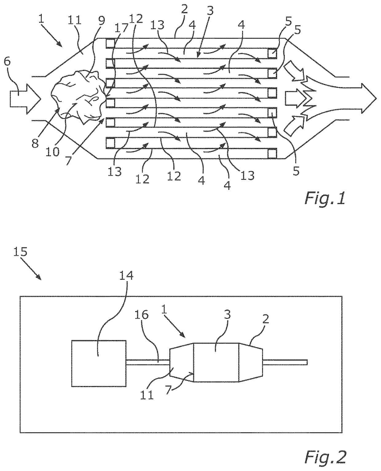
[0030]FIG. 1 shows a particle filter 1 in a schematic sectional view. The particle filter 1 comprises a housing 2 in which a filter body 3 is arranged. The filter body 3 has a plurality of channels 4 which have exhaust gas flowing through them during operation and in the present case are closed at the end by schematically depicted plugs 5. A flow direction of the exhaust gas through the particle filter 1 is depicted by an arrow 6 in FIG. 1. An ash former 8 which is only schematically depicted is arranged in the present case at an input side of the end face 7 of the filter body 3 viewed in this flow direction. Ash is produced by burning off the ash former 8. This ash is then introduced into the filter body 3 with the exhaust gas.

[0031]The ash former 8 may be formed by a ball or a plurality of balls made of metal paper, for example. Accordingly, the ash former 8 comprises a carrier material 9 on which at least one non-combustible constituent 10 of t...


PUM

PropertyMeasurementUnit
Temperatureaaaaaaaaaa
Adhesivityaaaaaaaaaa

Abstract

A method for operating a particle filter of a vehicle includes creating an ash to be introduced into a filter body of the particle filter by arranging a carrier material of an ash former on an input side of an end face of the filter body, as viewed in a flow direction of an exhaust gas through the particle filter, and combusting the carrier material, where a non-combustible constituent of the ash former is arranged on the carrier material. The created ash is then introduced into the filter body of the particle filter.

Description

CROSS REFERENCE TO RELATED APPLICATIONS[0001]This application is a continuation of PCT International Application No. PCT / EP2018 / 076092, filed Sep. 26, 2018, which claims priority under 35 U.S.C. § 119 from German Patent Application No. 10 2017 219 940.7, filed Nov. 9, 2017, the entire disclosures of which are herein expressly incorporated by reference.BACKGROUND AND SUMMARY OF THE INVENTION[0002]The invention relates to a method for operating a particle filter of a vehicle in which ash is introduced into a filter body of the particle filter. At least one ash former is combusted for this purpose.[0003]Exhaust gas systems for drawing off and cleaning exhaust gases from an internal combustion engine may exhibit a particle filter. A particle filter filters ash and soot particles, in particular, from the exhaust gas and these are then deposited in the filter material. In many particle filters for gasoline engines the effect described below may occur in this case. Large particles are filt...

Claims


Application Information

Patent Timeline
IPC IPC(8): F01N3/023F01N3/035B01D46/00
CPCB01D46/0027F01N3/0232F01N3/035F01N9/00F01N3/022F01N2510/06F01N2550/20F01N2900/14F01N3/029Y02T10/40F01N2610/12F01N2510/00F01N3/021
Inventor ALIG, ROBERT
Owner BAYERISCHE MOTOREN WERKE AG
Why Eureka
Try Eureka