
Method and device for bus addressing, and method and device for providing information

a technology of bus addressing and information, applied in the field of communication technology, can solve the problems of limited expansion of the control system employing high-speed serial buses, and achieve the effect of ensuring the efficiency and quality of exchanging information and the control system

Active Publication Date: 2020-09-03
SZ DJI TECH CO LTD
View PDF0 Cites 0 Cited by
  • Summary
  • Abstract
  • Description
  • Claims
  • Application Information

AI Technical Summary

Benefits of technology

The patent is about a new technology that allows components of a control system to communicate with each other using a field bus. Each component has a unique communication address, which ensures efficient and quality information exchange between components and the controller. The controller can also assign communication addresses to components, expanding the control system's capacity. The technology allows for real-time monitoring and display of the operational status of each component, improving user experience. Additionally, the controller can search for the index number and operational status of a component and provide the information to the user in a timely manner. Overall, the patent provides a solution for enhancing communication and operational efficiency in control systems.

Problems solved by technology

However, an expansion of the control system employing high speed serial bus is limited as the high speed serial bus is not addressable.

Method used


Image

  • Method and device for bus addressing, and method and device for providing information
  • Method and device for bus addressing, and method and device for providing information
  • Method and device for bus addressing, and method and device for providing information

Examples


first embodiment

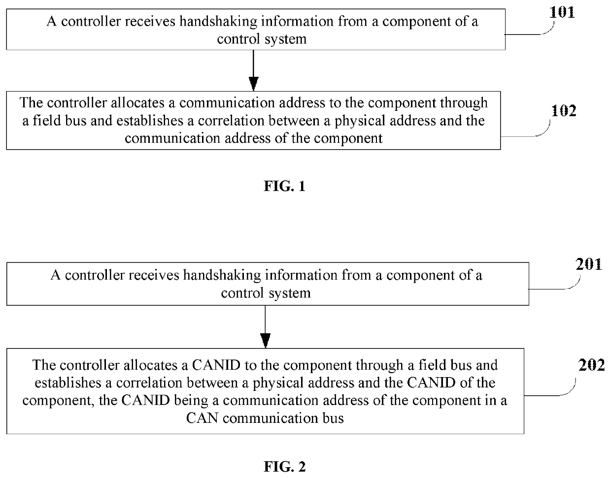
[0097]FIG. 1 shows an example of a flowchart of a method for bus addressing of a first embodiment in accordance with a first aspect of the disclosure. As shown in FIG. 1, the method can comprise steps 101 and 102.

[0098]In step 101, a process can be performed in which a controller can receive handshaking information from a component of a control system.

[0099]In step 102, a process can be performed in which the controller can allocate a communication address to the component through a field bus and establish a correlation between a physical address and the communication address of the component.

[0100]It will be appreciated that, a field of application and a type of the control system are not limited, and a function and a type of the components of the control system are not limited.

[0101]In some embodiments, the component of the control system can first send handshaking information to the controller. Upon receiving the handshaking information, the controller can allocate a communicatio...

second embodiment

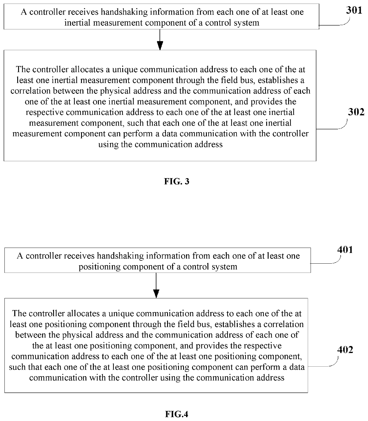
[0111]FIG. 2 shows an example of a flowchart of a method for bus addressing of a second embodiment in accordance with a first aspect of the disclosure. As shown in FIG. 2, the method can comprise steps 201 and 202.

[0112]In step 201, a process can be performed in which a controller receives handshaking information from a component of a control system.

[0113]In step 202, a process can be performed in which the controller allocates a Controller Area Network Identification (CANID) to the component through a field bus and establishes a correlation between a physical address and the CANID of the component, the CANID being a communication address of the component in a CAN communication bus.

[0114]The CAN field bus is a content-oriented addressing solution, therefore a control system can be established with a high performance and flexibility. A new node can be added to the CAN bus without modifying the hardware or software configuration. The CANID can be used to effect an arbitration in the C...


PUM


Abstract

A method for bus addressing includes receiving handshaking information from a component of a control system of an unmanned aerial vehicle (UAV), allocating a communication address to the component through a field bus, receiving a user instruction indicative of an index number of the component through a configuration interface, and establishing a correlation between a physical address of the component, the communication address, and the index number. The index number is configured to identify the component.

Description

CROSS-REFERENCE TO RELATED APPLICATIONS[0001]This application is a continuation of application Ser. No. 15 / 978,774, filed on May 14, 2018, which is a continuation of International Application No. PCT / CN2015 / 094913, filed on Nov. 18, 2015, the entire contents of both of which are incorporated herein by reference.TECHNICAL FIELD[0002]The disclosure relates to communication technology, more particularly to a method and a device for bus addressing and a method and a device for providing information.BACKGROUND OF THE DISCLOSURE[0003]High speed serial bus is a standard computer peripheral bus having advantages such as hot plugging, high performance and low system cost. High speed serial bus is widely used in control systems of automatic control, aviation, aerospace, navigation and unmanned aerial vehicle.[0004]Continuous development of technology demands a continuous update of the control systems to satisfy new applications. However, an expansion of the control system employing high speed...

Claims


Application Information

Patent Timeline
Patent Type & Authority Applications(United States)
IPC IPC(8): H04L29/12H04L12/40
CPCH04L12/40013H04L2012/40215H04L61/2038H04L61/6027H04L61/5038H04L2101/627
Inventor PAN, GUOXIUFENG, XIAOFENGSHI, RENLIDU, SHAOHE
Owner SZ DJI TECH CO LTD
Learn More