
Cruciate replacing artificial knee

Active Publication Date: 2020-09-10
GARINO JONATHAN P
View PDF0 Cites 2 Cited by
  • Summary
  • Abstract
  • Description
  • Claims
  • Application Information

AI Technical Summary

Benefits of technology

The patent text describes different versions of a knee joint prosthesis that can move between an extended position and a flexion position. The prosthesis includes a femoral component and a tibial component that are connected together to form the joint. The prosthesis also includes posts and cam recesses that enable smooth movement and can be engaged in either the extended or flexion position. Additionally, the text mentions the use of an artificial ligament to simulate either an anterior or posterior cruciate ligament. The patent text presents these various versions of the knee joint prosthesis with the goal of providing improved outcomes and patient satisfaction.

Problems solved by technology

But this artificial material is typically only used to replace the PCL and not the ACL.
The lack of an anatomically correct replacement may result in a TKR having reduced functionality as compared to the original knee.
This may create difficulties during physical therapy following surgery, as well as limit the patient's ability or desire to participate in physical activity following therapy.
Virtually all modern total knee replacements sacrifice the ACL or inadequately substitute it with a crude cam and post mechanism, thus leaving the reconstructed knee with kinematics similar to that of an ACL-deficient knee.
Normal knee kinematics therefore remain elusive.
In addition, the lack of proper interplay between an ACL and PCL (which together drive normal knee kinematics) leaves the TKR reconstruction short of producing a relatively normal knee for the patient.

Method used


Image

  • Cruciate replacing artificial knee
  • Cruciate replacing artificial knee
  • Cruciate replacing artificial knee

Examples


Embodiment Construction

[0040]The present invention provides various embodiments of a knee joint prosthesis. In the figures, ‘A’ represents the anterior side or direction, ‘P’ represents the posterior side or direction, ‘M’ represents the medial side or direction, ‘L’ represents the lateral side or direction, ‘F’ represents a femoral component, and ‘T’ represents a tibial component (or an articular insert that forms part of a tibial component).

[0041]FIG. 7A is a cross-sectional side elevation view of a knee joint prosthesis 100, as viewed in a sagittal plane, according to an exemplary embodiment of the present invention, wherein the knee joint prosthesis 100 is shown in an extended position. FIG. 7B is another view of the knee joint prosthesis 100 of FIG. 7A, wherein the knee joint prosthesis 100 is shown in a flexion position. The knee joint prosthesis 100 is capable of rotating between the extended position of FIG. 7A and the flexion position of FIG. 7B.

[0042]The prosthesis 100 generally comprises a femo...


PUM


Abstract

A knee joint prosthesis is capable of moving between an extended position and a flexion position. The knee joint prosthesis includes a femoral component that is configured to be mounted to a femur, a tibial component that is configured to be mounted to a tibia, a post fixedly connected to one of the femoral component and the tibial component, and a cam recess defined on the other of the femoral component and the tibial component that is configured to be engaged by the post in either the extended position or the flexion position of the knee joint prosthesis. The knee joint prosthesis may also include an artificial ligament that extends between the femoral component and the tibial component. The post and the ligament mimic one of the ACL and PCL.

Description

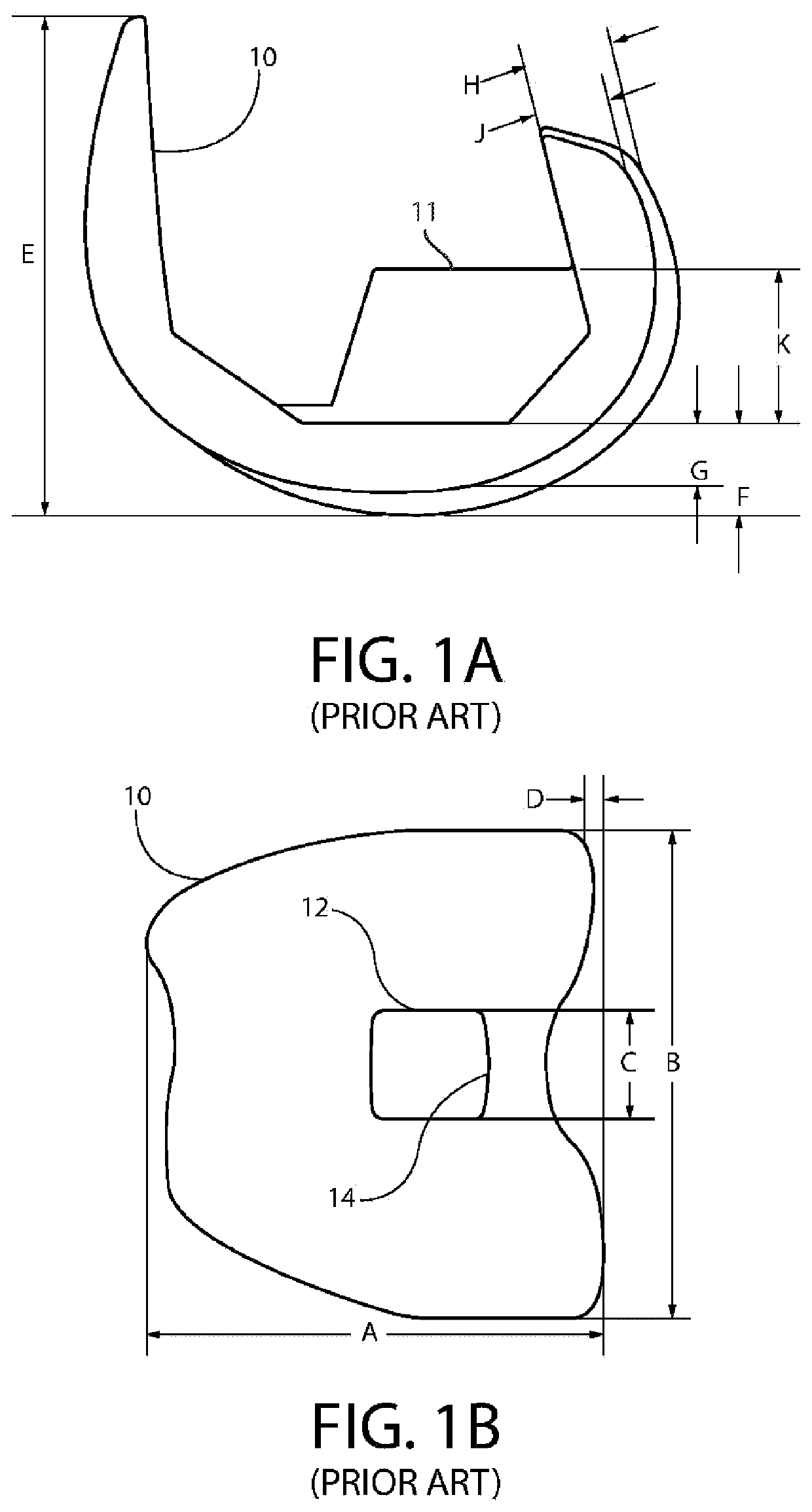
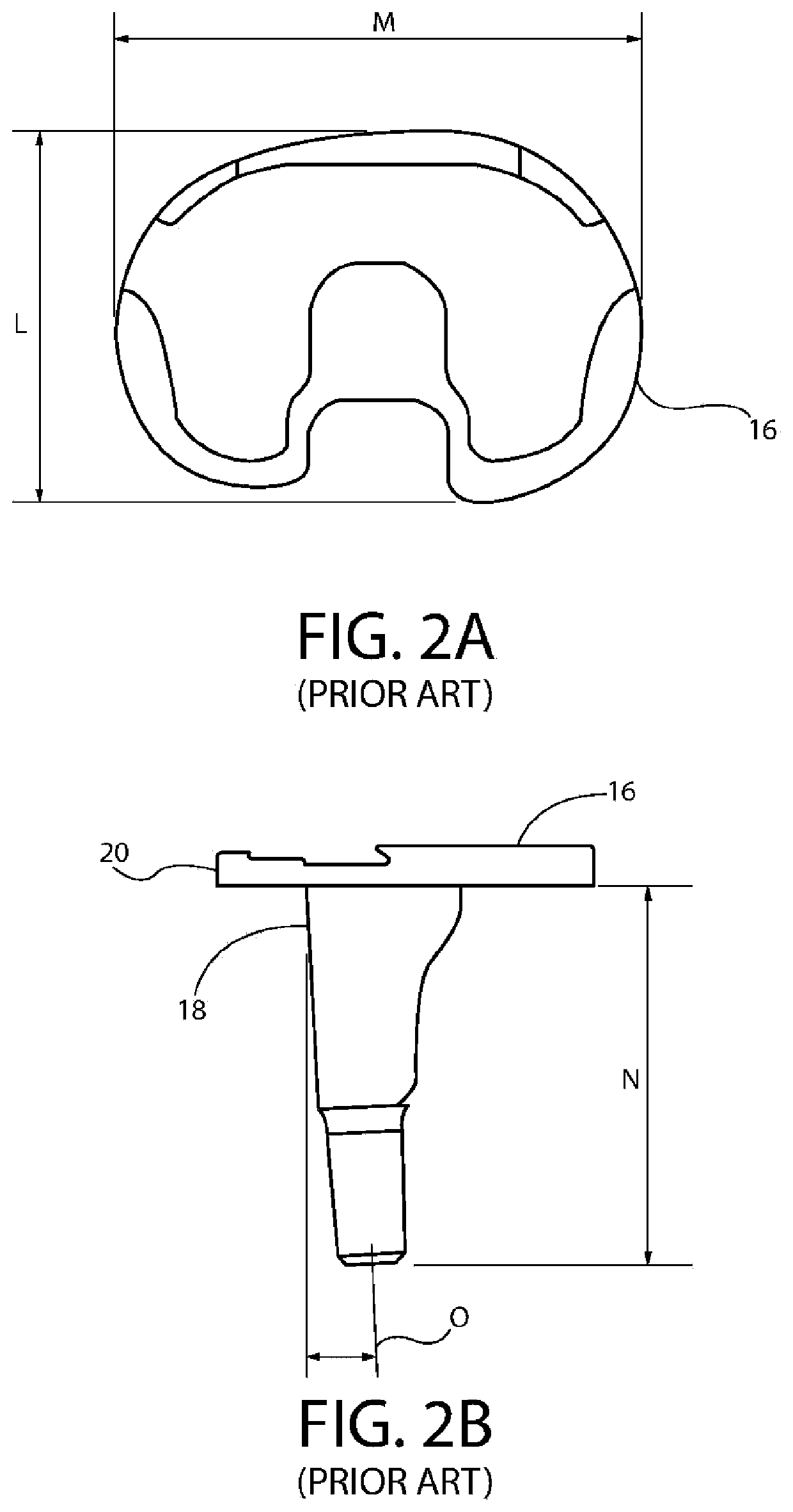
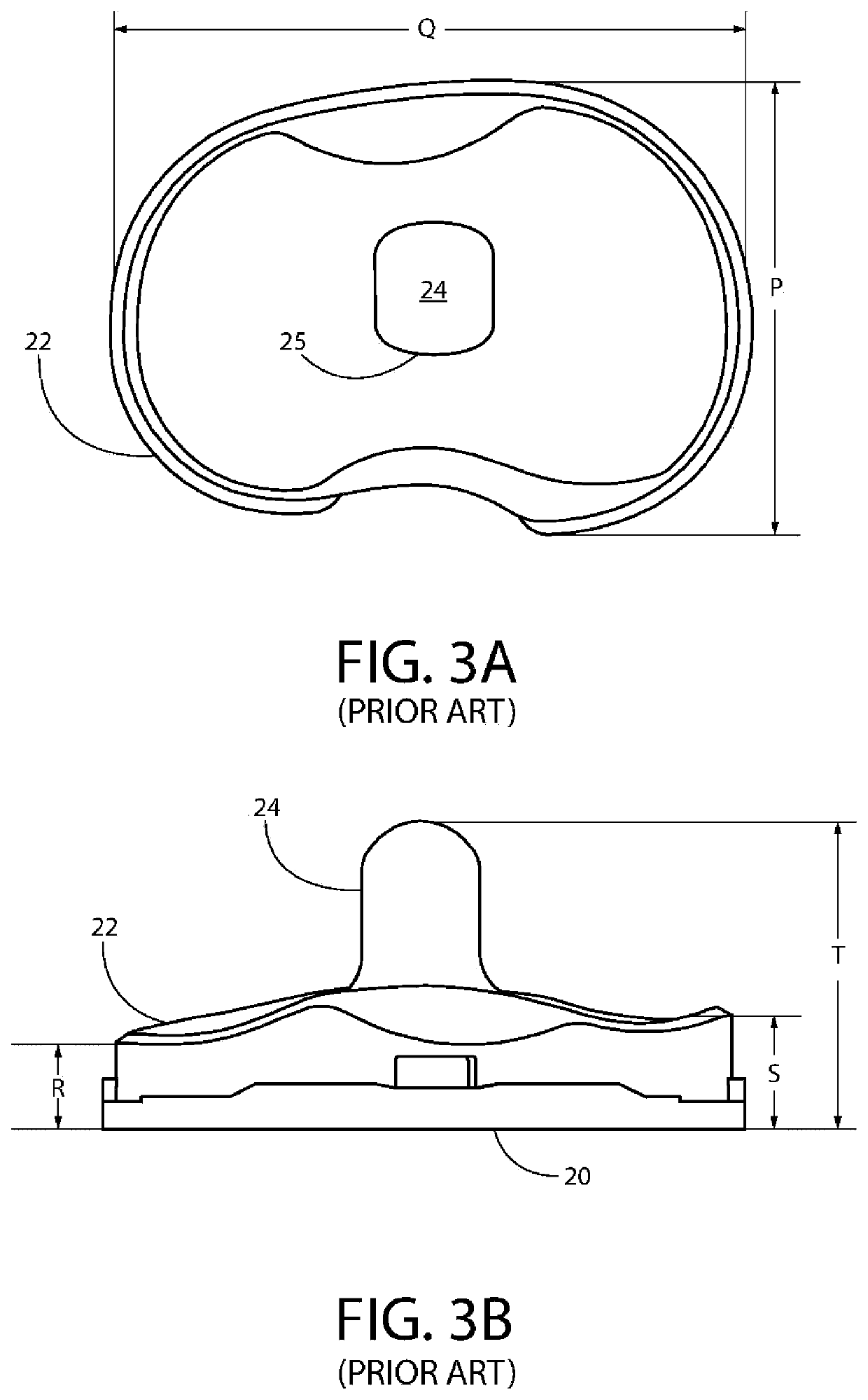
FIELD OF THE INVENTION[0001]This invention relates generally to artificial knee prostheses used for Total Knee Replacement (TKR), and more particularly, to a knee joint prosthesis having an artificial anterior cruciate ligament (ACL) and / or posterior cruciate ligament (PCL).BACKGROUND OF THE INVENTION[0002]As is described in U.S. Patent App. Pub. No. 2017 / 0252173 to Garino, which is incorporated by reference herein in its entirety and for all purposes, prosthetic knees generally include three main components, a femoral component (FIGS. 1A and 1B), which is attached to the distal end of the femur, a tibial component (FIGS. 2A and 2B), which is implanted onto the proximal end of the tibia, and an articular insert (FIGS. 3A and 3B), which is mounted onto the tibial component and provides a frictional surface for the femoral component. The components are designed to simulate a joint and the associated mechanics of a human knee throughout the knee's range of motion. The components are ge...

Claims


Application Information

Patent Timeline
IPC IPC(8): A61F2/38
CPCA61F2/389A61F2002/30523A61F2/3836A61F2002/30621A61F2/3859A61F2/38A61F2220/0025A61F2220/0033A61F2002/30362A61F2/3886A61F2/08A61F2002/30369A61F2002/30462A61F2002/30518
Inventor GARINO, JONATHAN P.
Owner GARINO JONATHAN P
Learn More