Image forming apparatus
- Summary
- Abstract
- Description
- Claims
- Application Information
AI Technical Summary
Benefits of technology
Problems solved by technology
Method used
Image

Examples
first embodiment
[0033]A structure of an image forming apparatus 100 according to the present invention in a first embodiment will be described with reference to FIGS. 1 to 5.
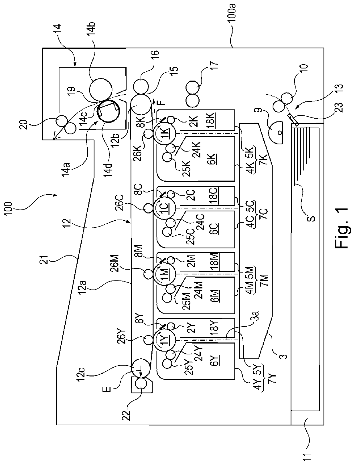
[0034]The structure of the image forming apparatus 100 including an intermediary transfer belt 12a will be described. FIG. 1 is a sectional view showing the structure of the image forming apparatus 100 including the intermediary transfer belt 12a. The image forming apparatus 100 is an example of a color laser printer. The image forming apparatus 100 shown in FIG. 1 includes four (plurality of) photosensitive drums 1Y, 1M, 1C and 1K as image bearing members corresponding to colors of yellow (Y), magenta (M), cyan (C) and black (K), respectively. Incidentally, for convenience of explanation, description is made using the photosensitive drum 1 representing the photosensitive drums 1Y, 1M, 1C and 1K in some cases. This is true for other image forming process means.
[0035]Each photosensitive drum 1 is rotationally driven in a clockwi...
modified embodiment
[0123]The transmission ratio i (=10) in this embodiment is a large transmission ratio i. For this reason, for example, even when the number of teeth Z1 of the driving roller gear 29 is 149 (=150−1), and the number of teeth Z2 of the motor gear 30 is 15, the transmission ratio i (=Z1 / Z2=149 / 15=9.93) is not changed remarkably. For this reason, the color misregistration in the entirety of the image forming apparatus 100 can be suppressed.
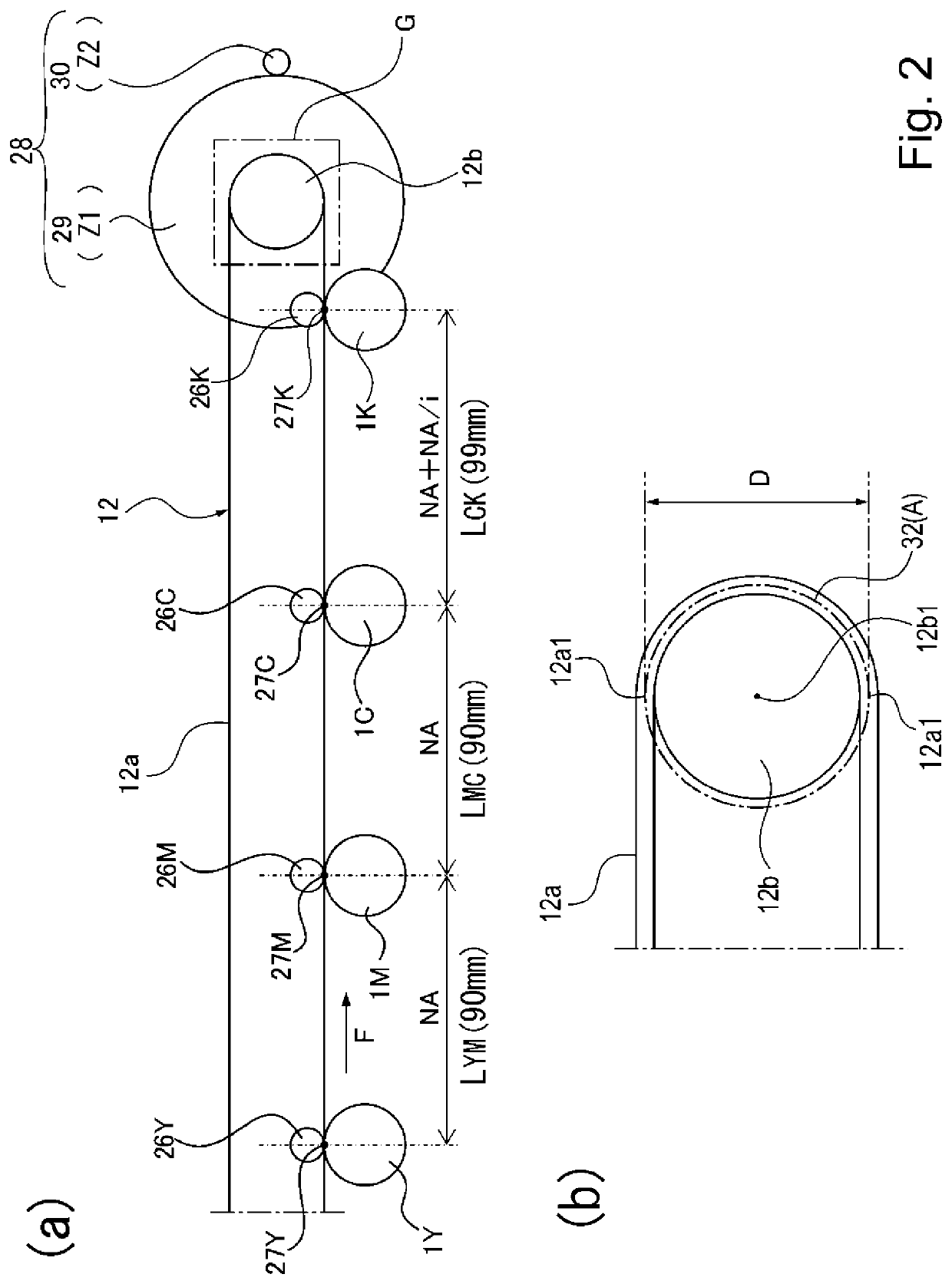
[0124]Also in this case, the inter-transfer-position distance LMC as the first inter-transfer-position distance between the primary transfer position 27M for the magenta M and the primary transfer position 27C for the cyan C which are disposed adjacent to each other along the intermediary transfer belt 12a is “N×A”. Here, N (N: integer) is the number of rotations at which the driving roller 12b rotates during movement of the predetermined position of the center 12a1 of the intermediary transfer belt 12a with respect to the thickness direction, and is “...
second embodiment
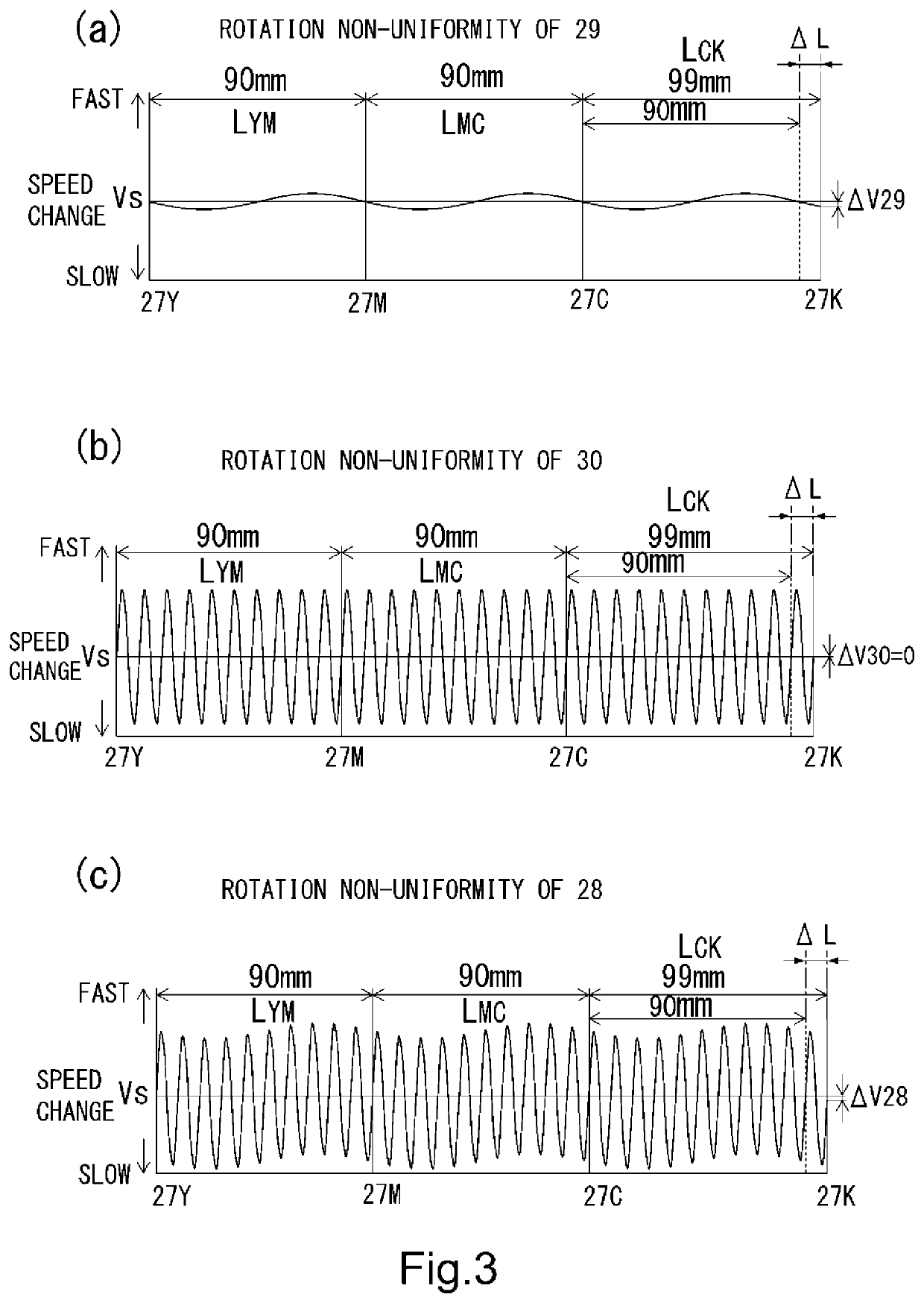
[0140]Next, by using FIGS. 6 to 9, a structure of an image forming apparatus 100 according to the present invention in a second embodiment will be described. Incidentally, constituent elements similar to those in the first embodiment described above are represented by the same reference numerals or symbols or by different reference numerals or symbols in some instances, and will be omitted from description. Part (a) of FIG. 6 is a sectional view showing a structure of a drive transmission device 28 for the intermediary transfer belt 12a in this embodiment, and part (b) of FIG. 6 is an enlarged view of a portion G shown in part (a) of FIG. 6. Part (a) of FIG. 7 is an illustration of a relationship between rotation non-uniformity of a driving roller gear 29 alone and each primary transfer position 27 in this embodiment, and part (b) of FIG. 7 is an illustration of a relationship between rotation non-uniformity of a driving roller pre-stage gear alone and each primary transfer position...
PUM
 Abstract
Description
Claims
Application Information
 - R&D
- Intellectual Property
- Life Sciences
- Materials
- Tech Scout
- Unparalleled Data Quality
- Higher Quality Content
- 60% Fewer Hallucinations
Browse by: Latest US Patents, China's latest patents, Technical Efficacy Thesaurus, Application Domain, Technology Topic, Popular Technical Reports.
© 2025 PatSnap. All rights reserved.Legal|Privacy policy|Modern Slavery Act Transparency Statement|Sitemap|About US| Contact US: help@patsnap.com