Image processing apparatus and image processing method, and image capturing apparatus

a technology of image processing and image processing method, applied in the field of image processing apparatus, image processing method, image capturing apparatus, can solve the problem that relighting processing is not performed on subjects other than persons, and achieve the effect of reducing unnaturalness

Active Publication Date: 2020-09-10
CANON KK
View PDF0 Cites 2 Cited by
  • Summary
  • Abstract
  • Description
  • Claims
  • Application Information

AI Technical Summary

Benefits of technology

[0006]The present invention has been made in consideration of the above situation, and reduces unnaturalness in a result of the relighting processing in a scene where a scene to be processed includes a subject detected by subject detection and a subject not detected by subject detection.

Problems solved by technology

For example, in the case of subject detection using human face detection, there is a problem in that relighting processing is not performed on subjects other than persons whose faces are detected.
Therefore, a result of the relighting processing exhibits an unnatural image, as shown in FIG. 15D, such that only the person becomes bright, and the dog next to the person remains dark.

Method used


Image

  • Image processing apparatus and image processing method, and image capturing apparatus
  • Image processing apparatus and image processing method, and image capturing apparatus
  • Image processing apparatus and image processing method, and image capturing apparatus

Examples


first embodiment

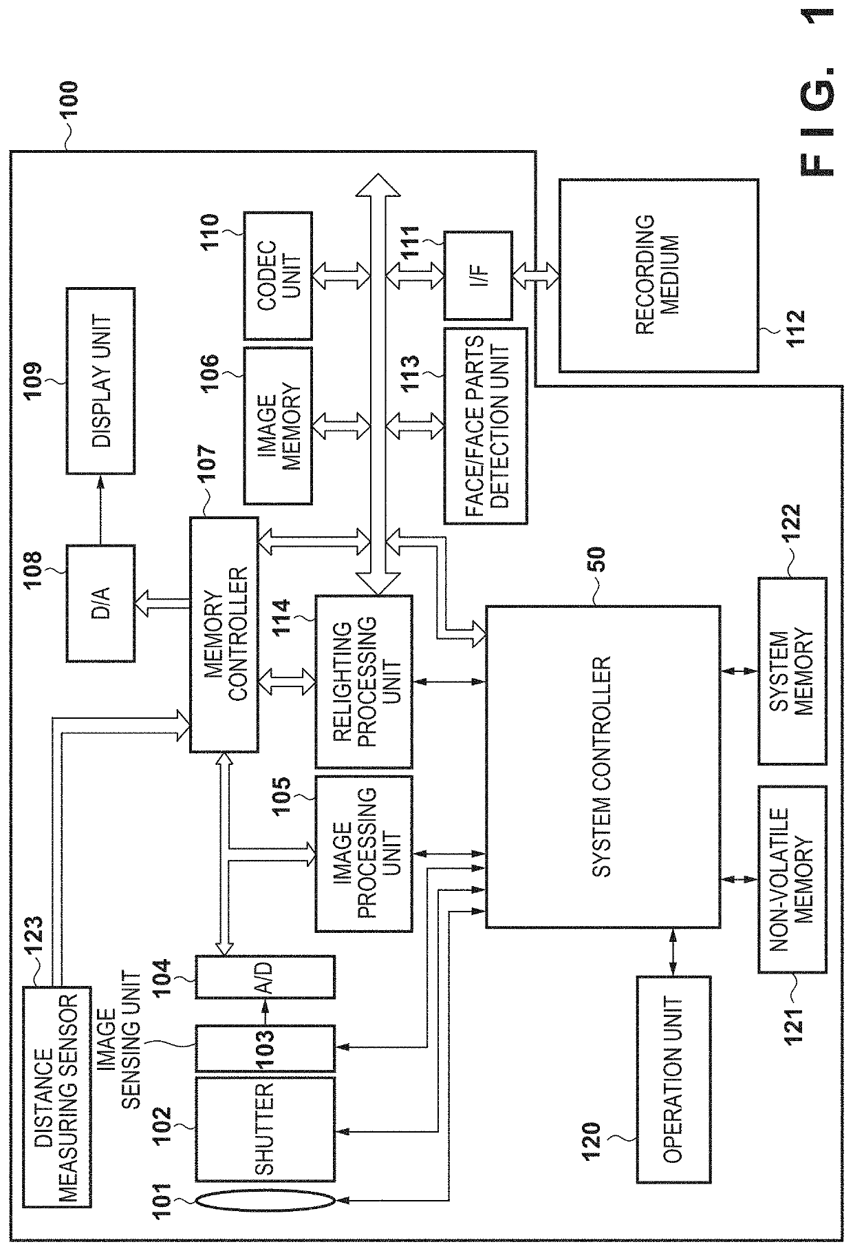
[0036]FIG. 1 is a block diagram showing a configuration of a digital camera 100 according to an embodiment of the present invention. In the digital camera 100 shown in FIG. 1, light entering via a lens group 101 (imaging optical system) including a zoom lens and a focus lens and a shutter 102 having an aperture stop function is photoelectrically converted in an imaging unit 103. The imaging unit 103 is configured by a CCD, a CMOS sensor, or the like, and an electric signal obtained by photoelectric conversion is outputted to an A / D converter 104 as an image signal. The A / D converter 104 converts an analog image signal output from the imaging unit 103 into a digital image signal (image data) and outputs the digital image signal (image data) to the image processing unit 105.

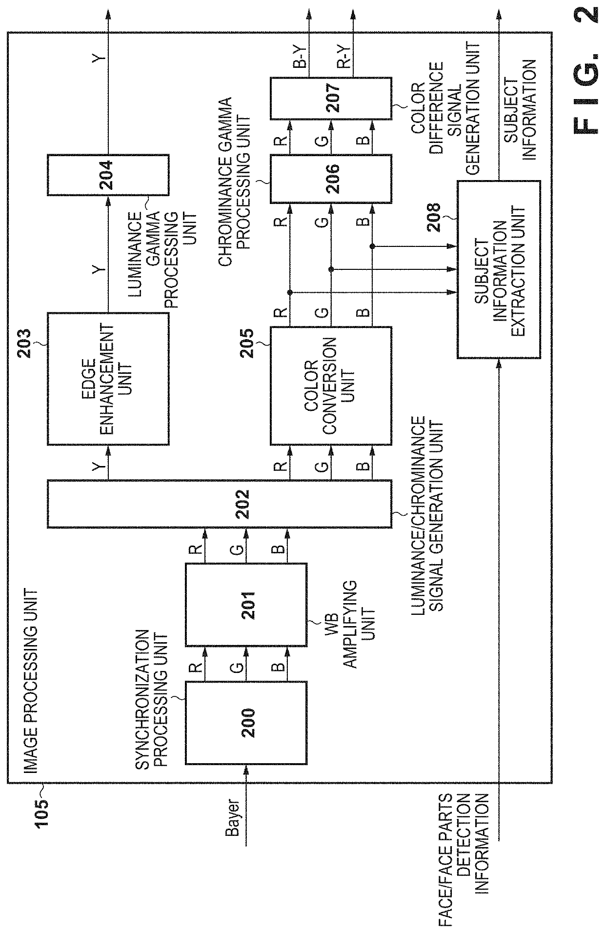
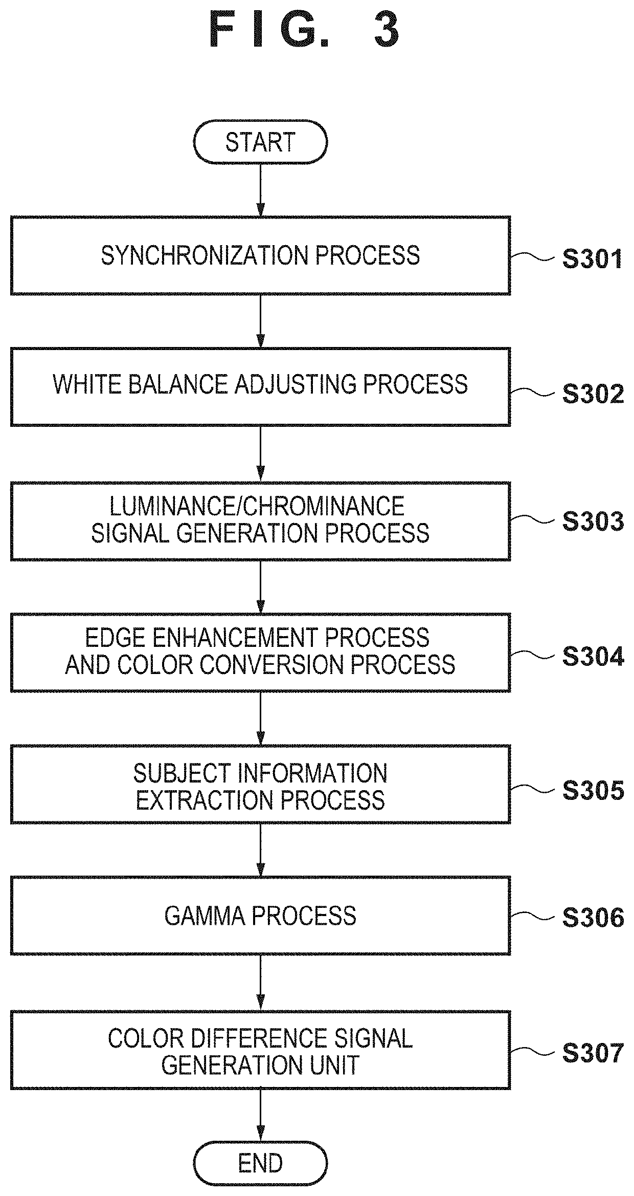
[0037]The image processing unit 105 performs various image processing including color conversion processing such as white balance processing, y processing, contour enhancement processing, and color correction proce...

second embodiment

[0093]Next, a second embodiment of the present invention will be described. In the second embodiment, a user specifies a subject subjected to the relighting processing by using the display unit 109 and the operation unit 120, and the relighting processing by the relighting processing unit 114 is performed on the specified subject.

[0094]FIG. 13 is a flowchart showing the relighting processing in the second embodiment. Since steps S901 to S905 and S907 to S909 are the same as the processes described in FIG. 9, thus description thereof will be omitted. Hereinafter, only the processes in steps S1301 to S1303 not described in FIG. 9 will be described.

[0095]If it is determined in step S905 that another subject exists within the distance range of the main subject in the subject peripheral region, then in step S1301, the main subject and the other subject in the subject peripheral region are displayed in an emphasized manner in the display unit 109 to show that the main subject and the othe...


PUM


Abstract

An image processing apparatus comprises: an acquisition unit that acquires a first image obtained through shooting and distance information of the first image; a detection unit that detects a main subject from the first image; an extraction unit that extracts another subject from the first image based on the distance information of the main subject; a setting unit that sets parameters of one or more virtual light sources that emit virtual light to the main subject and the extracted other subject; and a processing unit that generates from the first image a second image in which the main subject and the other subject are illuminated with the virtual light using the parameters set by the setting unit.

Description

BACKGROUND OF THE INVENTIONField of the Invention[0001]The present invention relates to an image processing apparatus, an image processing method, and an image capturing apparatus, and more particularly to a technique for correcting brightness of an input image.Description of the Related Art[0002]Conventionally, there has been known as a relighting processing a technique of irradiating a subject in a captured image with light from a virtual light source. The relighting process makes it possible to brighten a dark area such as a shadow caused by ambient light and obtain a preferable image.[0003]For example, Japanese Patent Laid-Open No. 2016-72694 discloses a relighting processing capable of appropriately correcting the state of a shadow of a subject. Specifically, the state of the shadow in a predetermined area of the captured image is detected, and the characteristics of the virtual light source are determined based on the detected state of the shadow. Then, the captured image is c...

Claims


Application Information

Patent Timeline
Patent Type & Authority Applications(United States)
IPC IPC(8): H04N5/243G06T7/50G06K9/62G06T5/00G06V10/141G06V10/145G06V10/60
CPCG06T2207/30201G06T5/00G06K9/6228G06T2207/20104H04N5/243G06T7/50G06T5/008G06T2207/20192G06T2207/10024H04N5/2621H04N9/74G06V40/166G06V10/141G06V10/145G06V10/60H04N23/611H04N23/71H04N23/10G06F18/211H04N23/76
Inventor WATAZAWA, NAOKO
Owner CANON KK
Why Eureka
Try Eureka