Switch circuit, high-frequency module, and communication apparatus
- Summary
- Abstract
- Description
- Claims
- Application Information
AI Technical Summary
Benefits of technology
Problems solved by technology
Method used
Image
Examples
first embodiment
Modification of First Embodiment
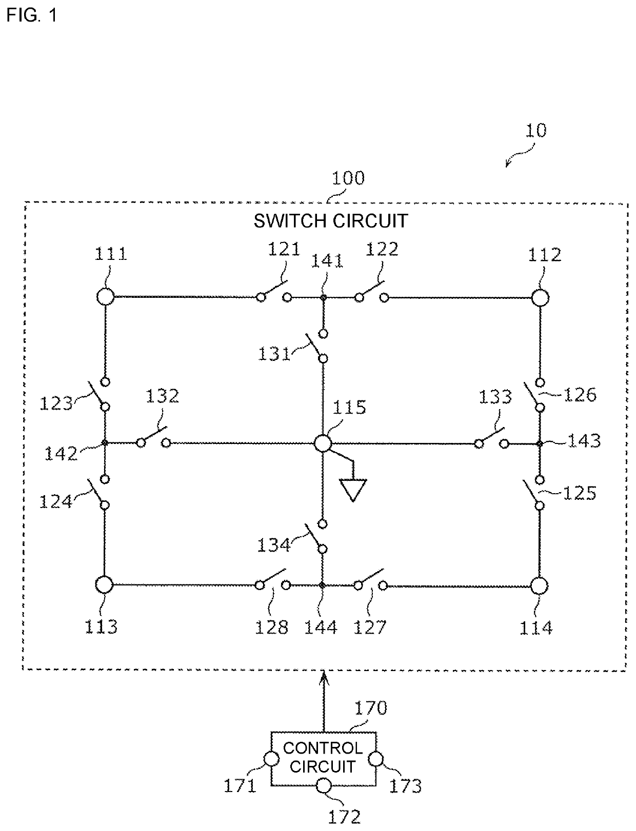
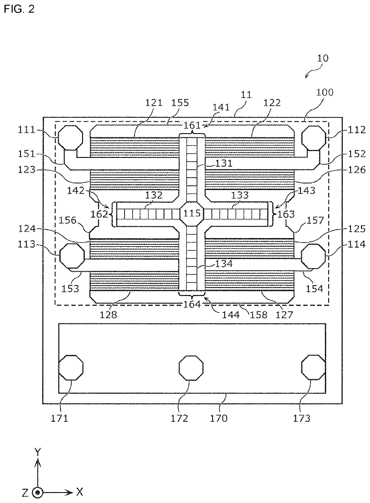
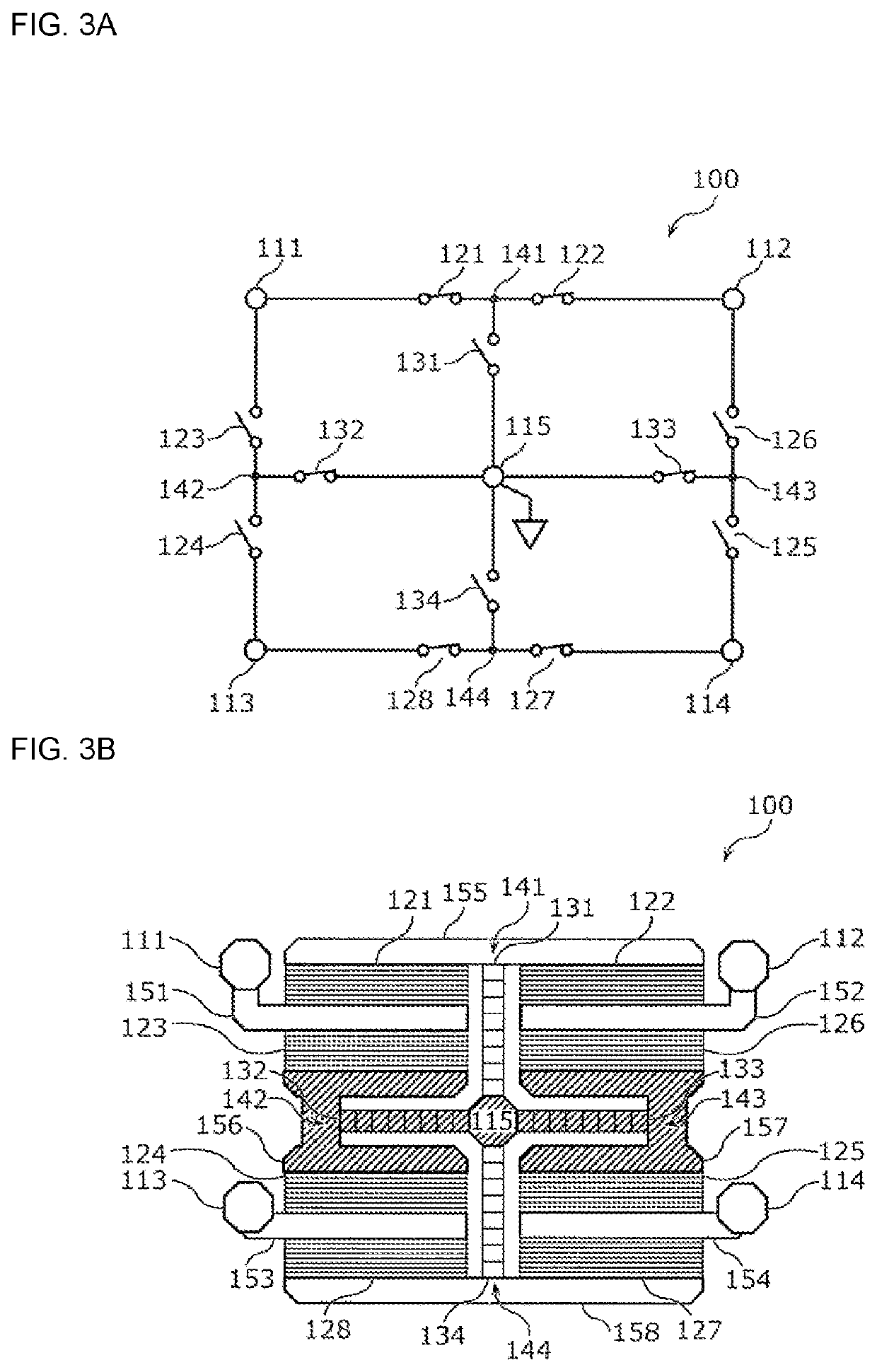
[0111]Next, a modification of the first embodiment will be described. In this modification, the shape of the sixth electrode connected to the second shunt switch and the shape of the seventh electrode connected to the third shunt switch are mainly different from those of the first embodiment. Hereinafter, the present modification will be described specifically with reference to FIG. 6 mainly with respect to points different from those in the first embodiment.
[0112]FIG. 6 is a plan view of a switch circuit 100A according to the modification of the first embodiment. The switch circuit 100A according to the present modification includes a sixth electrode 156A and a seventh electrode 157A instead of the sixth electrode 156 and the seventh electrode 157 in the first embodiment.
[0113]Similarly to the sixth electrode 156 in the first embodiment, the sixth electrode 156A is a wiring for connecting the third series switch 123, the fourth series switch 124, and...
second embodiment
[0118]Next, a description will be given of a second embodiment. In the present embodiment, an arrangement of the series switches is mainly different from that of the first embodiment. Hereinafter, the present embodiment will be described specifically with reference to FIG. 7, focusing on points different from those of the first embodiment. Note that, since the circuit configuration and operating states of the switch circuit according to the present embodiment are the same as those in the first embodiment except that the first to eighth series switches 121 to 128 are replaced by first to eighth series switches 221 to 228, the illustration and description thereof are omitted.
2.1 Arrangement of Circuit Elements in Switch Circuit 200
[0119]FIG. 7 is a plan view of a switch circuit 200 according to the second embodiment. The switch circuit 200 according to the present embodiment includes first to fourth terminals 211 to 214, the common ground terminal 115, first to eighth series switches ...
third embodiment
[0136]Next, a description will be given of a third embodiment. In the present embodiment, a case where the present disclosure is applied to a single-pole double-throw (SPDT) switch will be described. Hereinafter, the present embodiment will be described specifically with reference to FIG. 8 and FIG. 9, focusing on points different from those of the first and second embodiments described above.
3.1 Circuit Configuration of Switch Circuit 300
[0137]First, a circuit configuration of a switch circuit 300 according to the present embodiment will be described specifically with reference to FIG. 8. FIG. 8 is a circuit configuration diagram of the switch circuit 300 according to a third embodiment.
[0138]The switch circuit 300 is a so-called SPDT switch, and is mounted on a substrate. The switch circuit 300 includes first to third terminals 311 to 313, a common ground terminal 315, first to fourth series switches 321 to 324, and first and second shunt switches 331 and 332. The switch circuit 3...
PUM
 Abstract
Description
Claims
Application Information
 - R&D Engineer
- R&D Manager
- IP Professional
- Industry Leading Data Capabilities
- Powerful AI technology
- Patent DNA Extraction
Browse by: Latest US Patents, China's latest patents, Technical Efficacy Thesaurus, Application Domain, Technology Topic.
© 2024 PatSnap. All rights reserved.Legal|Privacy policy|Modern Slavery Act Transparency Statement|Sitemap


